background image

Lyric Gateway Installation and Reference Guide


- 17 -


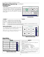
Mechanics of Programming

Mechanics of Programming

Mechanics of Programming

Mechanics of Programming    (Continued) 


Loading Factory Defaults

Loading Factory Defaults

Loading Factory Defaults

Loading Factory Defaults 

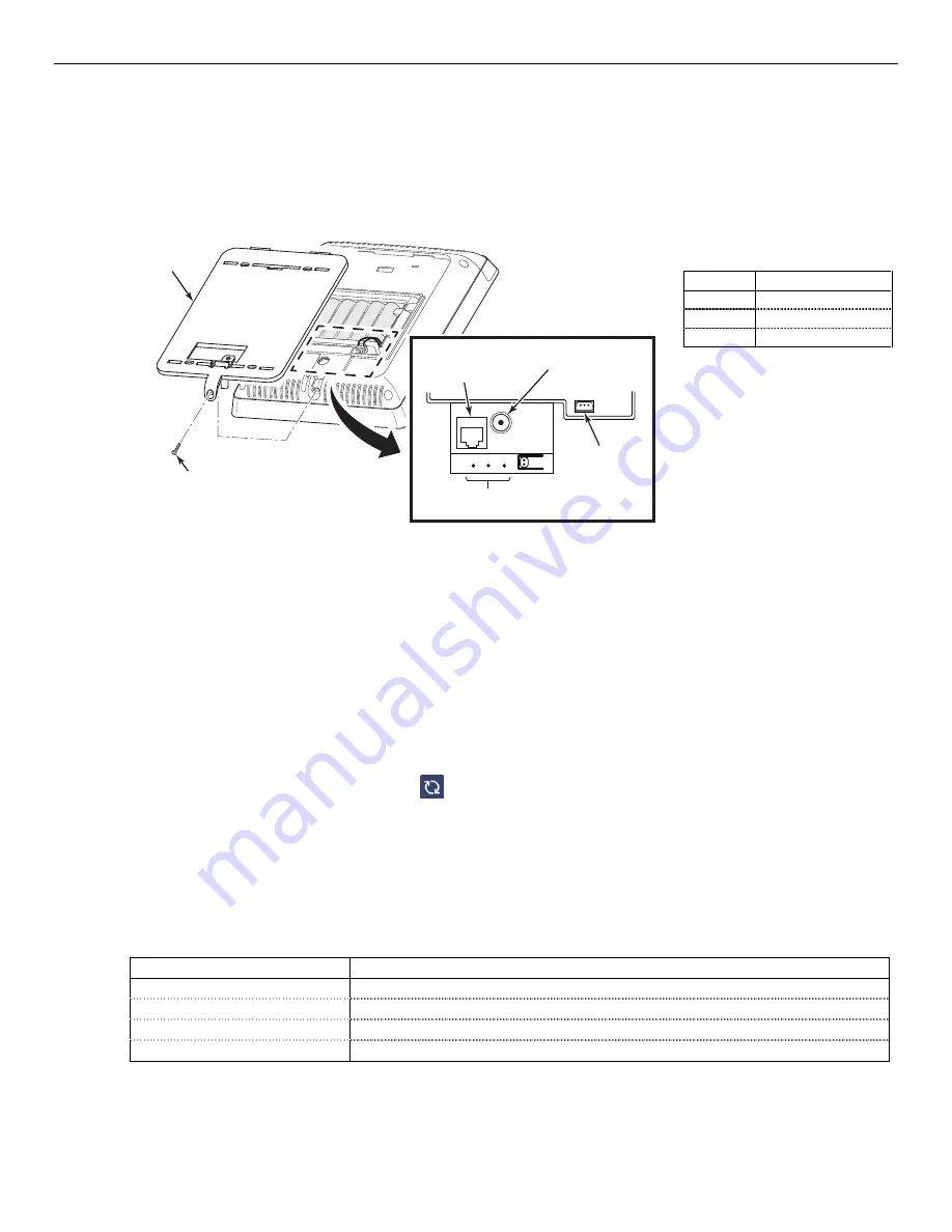
To load the factory defaults, refer to the following procedure. Refer to the Programming Values section of this 
manual to view the default values. 
1.  Remove the Gateway’s rear cover, the panel’s tamper alarm will sound. 
2.  Using a precision screwdriver, paperclip or equivalent, depress and hold the left (Default), recessed 

microswitch for 10-20 seconds and enter Installer Code when prompted.   


REAR COVER

SCREW

DETAIL A

MICROSWITCHES

RJ45

ETHERNET

RECEPTACLE

POWER SUPPLY
RECEPTACLE

BATTERY

RECEPTACLE

g

w

-ke

yp

a

d

-0

0

5

-V0


Recessed

Recessed

Recessed

Recessed    

Microswitch Functions

Microswitch Functions

Microswitch Functions

Microswitch Functions    

Location

Location

Location

Location    

Function

Function

Function

Function    

Left 

Factory Default 

Center 

Reboot 

Right 

WPS 


Exit

Exit

Exit

Exit    Program

Program

Program

Programming

ming

ming

ming    Mode

Mode

Mode

Mode


1.  Select the “

” key to exit the current screen OR select the Home key to return to the Home Screen.


Deleting Wireless Sensors, Keys and Keypads

Deleting Wireless Sensors, Keys and Keypads

Deleting Wireless Sensors, Keys and Keypads

Deleting Wireless Sensors, Keys and Keypads    

SiX™ Series or 5800 Sensors, Wireless Keys or Wireless Keypads must be deleted using AlarmNet 360. After 
entering AlarmNet 360 select the “Sensors”, “Keyfobs” or “Keypads” programming option (as applicable).  

NOTE: 

NOTE: 

NOTE: 

NOTE:     SiX™ Series sensors must be deleted from the Gateway before the device can be enrolled in another 

system.  

1.


  Select the Sensor, Keyfob or Keypad to be deleted from the displayed list. 

2.


  The system displays the programmed information for the associated device and confirm the deletion when 

prompted.  

3.


  When programming is complete select “

“ to Sync Changes and send the information to the gateway. 

Installing Z

Installing Z

Installing Z

Installing Z----Wave® Home Automation Devices 

Wave® Home Automation Devices 

Wave® Home Automation Devices 

Wave® Home Automation Devices     

The Lyric Gateway supports Z-Wave Home Automation Devices that can be included or excluded via AlarmNet 
360 or locally by the User.    Smart Scenes are User programmable functions and can be programmed via remote 
services or locally via the MyHome Gateway App. Refer to the Lyric Gateway User Reference Guide for detailed 
programming information. 

Programming via 

Programming via 

Programming via 

Programming via the 

the 

the 

the Alar

Alar

Alar

AlarmNet 360 App

mNet 360 App

mNet 360 App

mNet 360 App    

1.


  At the Installer Programming screen, select “Z-Wave Devices”.  The system displays the following options: 

Op

Op

Op

Option

tion

tion

tion    

Function

Function

Function

Function    

Include Devices 

Include (enroll) new Z-Wave Devices 

Exclude Devices 

Exclude (delete) Z-Wave Devices 

Factory Default Controller 

Reset the Z-Wave controller to the factory default settings. 

Retrieve Failed Devices 

Reset a failed-Wave Device 

2.


  When programming is complete follow the prompts to complete the function.  


Содержание Lyric LCP300-LC

Страница 1: ...Lyric Lyric Lyric Lyric Gateway Gateway Gateway Gateway Installation and Reference Guide Ref LCP300 L LCP300 LC 800 21666 10 16 Rev A ...

Страница 2: ...nnections to an AC source or phone lines are made If detectors are not so located a fire within the room could prevent the control from reporting a fire or an intrusion THIS CONTROL COMPLIES WITH NFPA REQUIREMENTS FOR TEMPORAL PULSE THIS CONTROL COMPLIES WITH NFPA REQUIREMENTS FOR TEMPORAL PULSE THIS CONTROL COMPLIES WITH NFPA REQUIREMENTS FOR TEMPORAL PULSE THIS CONTROL COMPLIES WITH NFPA REQUIRE...

Страница 3: ...Input Types 12 Transmitter Battery Life 12 RF Transmitter Loop Numbers 13 Mechanics Mechanics Mechanics Mechanics of of of of Programming Programming Programming Programming 14 Programming 14 Navigating 14 Gateway Touchpad 14 Gateway Menu Mode 14 Keypad Lockout 14 My Home Gateway Smart Device Touch screen Display 15 Navigation Keys 15 Home Screen 15 Navigating Menus 16 Security Screen 17 Master Us...

Страница 4: ...Agency Agency Notices Notices Notices Notices 37 SIA Quick Reference Guide SIA Quick Reference Guide SIA Quick Reference Guide SIA Quick Reference Guide 38 Specifications Specifications Specifications Specifications 39 Glossary Glossary Glossary Glossary 40 Contacting Technical Support Contacting Technical Support Contacting Technical Support Contacting Technical Support 41 Index Index Index Index...

Страница 5: ...re Medical Video Camera Control requires Wi Fi connection Supports Mobile Devices Tablet iPAD etc that duplicate functions of the Lyric Gateway i e Security Web Content Home Automation and Video Control Requires Android Operating System Version 4 4 or higher or iOS Version 8 0 or higher Wall or Desk mounting Home Automation Home Automation Home Automation Home Automation Integrated Z Wave Support ...

Страница 6: ...ramming Programming Programming Options stored in EEROM Can be uploaded downloaded or controlled via AlarmNet 360 using capable Cellular or Wi Fi Communications Module or Ethernet connection Flash Downloading Other Features Other Features Other Features Other Features Exit Error feature detects difference between an actual alarm and exit alarm caused by leaving a door open after the exit delay exp...

Страница 7: ...ckup Battery 1 Insert the battery pack into Gateway 2 Close the hinged battery retainer 3 Connect the battery pack connector to the receptacle on the Gateway 4 Align the slots on the back of the Gateway with the hooks on the rear cover wall mount as shown below 5 Once attached insert the screw to secure the rear cover wall mount 6 Plug the power supply into a 24 hour 110VAC unswitched outlet Upon ...

Страница 8: ...between 2 4GHz devices such as Wi Fi Routers Access Points For wall mounting follow the steps and refer to the figure below 1 Feed the field wiring through the appropriate openings in the wall mount 2 Attach the wall mount to a sturdy wall using the four provided screws 3 Install an additional mounting screw in the case tamper 4 Align the slots on the back of the Gateway with the hooks on the wall...

Страница 9: ...ed to the internet via a hardwire connection or wirelessly via the premise s Wi Fi router Programming is done via AlarmNet 360 using a Smart Mobile Device or a laptop computer For Wireless Installations the following are required A smart device with the AlarmNet 360 App loaded or a laptop referred to as the set up device The App will be used to connect the Gateway panel to the customer s router on...

Страница 10: ...ions Module is only available in the continental United States Alaska and Hawaii Alaska and Hawaii Alaska and Hawaii Alaska and Hawaii Model Model Model Model Description Description Description Description LYRIC 3G LYRIC 3GC GSM Cellular Communications Module LYRIC CDMA CDMA Cellular Communications Module LYRICLTE Series LTE Series Cellular Communications Modules Communications Module Communicati...

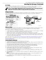
Страница 11: ...move Gateway upper cover bezel 4 Install the Cellular Communications Module into the Gateway 5 Ensure that the Communications Module is properly seated into the Gateway 6 Insert the cover bezel into the Gateway 7 Slide the cover bezel down to lock it in place and secure the Communications Module 8 Go to the AlarmNet 360 SETTINGS Page COMMUNICATOR Section and change Communication Path Internal Devi...

Страница 12: ... the missing transmitter zone number s and Supervision will be displayed The supervision for a particular transmitter in the system that may also be carried off the premises may be turned off by entering it as an Unsupervised type For additional information refer to the Zones programming section in the Lyric Gateway Quick Installation Guide p n 800 21668 5800 and SiX Series transmitters have built...

Страница 13: ...SED 5811 ENROLL AS SUPERVISED LOOP 4 LOOP 1 LOOP 2 LOOP 3 5818MNL ENROLL AS SUPERVISED LOOP 1 LOOPS 1 3 LOOP 1 5816MN ENROLL AS SUPERVISED LOOP 1 TERMINALS LOOP 3 TERMINALS ALTERNATE POSITION FOR LOOP 2 LOOP 3 TERMINALS 5821 ENROLL AS SUPERVISED 5820L ENROLL AS SUPERVISED 5819S WHS BRS ENROLL AS SUPERVISED LOOP 2 REED 5819S ENROLL AS SUPERVISED 5819 ENROLL AS SUPERVISED LOOP 2 REED LOOP 3 TERMINAL...

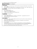
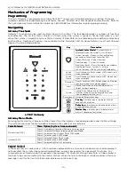
Страница 14: ... selected Disarmed Disarm Gateway LED flashes green until code is entered then turns steady green Alert Flashes red when an alert condition exists Select to hear condition Cancel Cancel User Code entry or Emergency Flashes white during an emergency and silence beeping due to faults Emergency Activates Emergency keys Fire key Fire key Fire key Fire key Initiates panic fire alarm within 5 seconds of...

Страница 15: ...n Selecting the key or the Home cancel key will return you to the previous screen or the home screen as applicable at any time By touching selecting an icon or key the system depending on the function advances to another screen toggles between options or scrolls through multiple options that can be selected The system provides a prompt when a specific input is required Home Screen Home Screen Home...

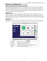
Страница 16: ...User User User Menu Menu Menu Menu Screen Screen Screen Screen The Master User Menu screen provides access to the User configurable features Entering the Master User Code is required to access the User Tools Menu Refer to the Lyric Gateway User Reference Guide p n 800 21670 or higher for additional information gw_keypad 016 V1 Advanced Network Config Ready To Arm Home Paired Devices Users Events E...

Страница 17: ...armNet 360 After entering AlarmNet 360 select the Sensors Keyfobs or Keypads programming option as applicable NOTE NOTE NOTE NOTE SiX Series sensors must be deleted from the Gateway before the device can be enrolled in another system 1 Select the Sensor Keyfob or Keypad to be deleted from the displayed list 2 The system displays the programmed information for the associated device and confirm the ...

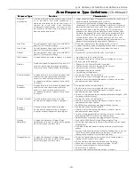
Страница 18: ...covers a sensitive area i e stock room drug supply room etc It can also be used on a sensor or contact in an area where immediate notification of an entry is desired Instant alarm when armed in Away Home Stay Arm Night Stay or Home Stay Instant or Away Instant night mode Provides a latched trouble sounding from the keypad and if desired a Central Station report when disarmed day 24 hour Silent Ala...

Страница 19: ... No keypad sounding or chime System can still be armed General Monitor Assigned sensors or contacts on doors and windows or asset protection within the premises Used to track activity of the occupant and alert occupant of the activity of others No reports to the Central Station Fault restore events are logged by the system Monitors entry into a monitored area Activates a one time announcement when...

Страница 20: ...Function Function 995 Fire Emergency 996 Medical Emergency 999 Police Emergency NOTE NOTE NOTE NOTE The Emergency panic functions can only be activated from the Gateway touchpad or the Lyric Keypad Security Codes Security Codes Security Codes Security Codes Installer Code Installer Code Installer Code Installer Code The installer programs the 4 digit Installer Code initially as part of the program...

Страница 21: ...e system only if it was used to arm it In addition the Installer Code cannot disarm the system if it was armed by pressing and holding a Quick Arm button The Guest Code can disarm the system only if it was used to arm it In addition the Guest Code cannot disarm the system if it was armed by pressing and holding a Quick Arm button Duress code sends a special code to the Central Station when used to...

Страница 22: ...mm Trouble Automation Icon Z Wave Node Failure OR Z Wave Controller Not Ready Ready To Arm 988 RF Jam 5800 Series Wireless Device Garage Door Open Armed Away 990 RF Jam SiX Series Wireless Device Armed Home Stay Door Open Armed Night Home Stay Window Open Armed Custom Fire OR Heat Sensor Restart Timer Environmental Battery Low Flood Bypassed Zones Glass Break CO Alarm Medical Alarm Reporter Failur...

Страница 23: ...nd sirens and keypad sounds are discontinued The Gateway transmits a beep acknowledgment to the Central Station once per second The beep alternates between two tones and indicates that the Gateway is waiting for a session command from the Central Station operator Once a command is issued the beep acknowledgement is discontinued however if a command is not issued within two minutes the system will ...

Страница 24: ...m Interior Interior 134 Alarm Entry Exit Entry Exit 135 Alarm Day Night Day Night 137 Alarm Tamper Tamper 145 Expansion Module Tamper Expansion Module Tamper 146 Silent Burglary Silent Burglary 150 24 Hour Non Burglary 24 Hour Non Burglary 162 Carbon Monoxide Detected Carbon Monoxide Detected 301 Trouble AC Loss AC Loss 302 Trouble Low System Battery Low system battery 305 Trouble System Reset Sys...

Страница 25: ...ermostat Mode Heat Thermostat Mode Heat 3402 Thermostat Mode Cool Thermostat Mode Cool 3403 Thermostat Mode Auto Thermostat Mode Auto 3404 Thermostat Mode Aux Em Heat Thermostat Mode Aux Em Heat 3405 Thermostat Fan Mode Auto Thermostat Fan Mode Auto 3406 Thermostat Fan Mode Manual On Thermostat Fan Mode Manual On 3407 Thermostat Fan Mode Circulate Thermostat Fan Mode Circulate 3408 Thermostat Set ...

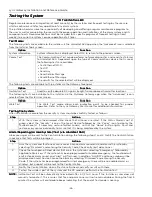
Страница 26: ...nal information Testing the System Testing the System Testing the System Testing the System After installation is completed the security system should be carefully tested as follows Step Step Step Step Action Action Action Action 1 With the system in the disarmed state check that all zones are intact If the Status Shield is not lit green select the Security icon on the Smart Device followed by the...

Страница 27: ...ing the transmitters permanently This mode is similar to the RF Sniffer Mode except that the wireless receiver gain is reduced This will enable you to make sure that the RF signal from each transmitter is received with sufficient signal amplitude when the system is in the normal operating mode During Go No Go mode the system beeps every 30 40 seconds Enter Go No Enter Go No Enter Go No Enter Go No...

Страница 28: ...A Communications Module DMA Communications Module Message Message Message Message Function Function Function Function Cell Phone Type CDMA Model Displays model number i e SL3010T ESN MEID Displays Device s 32 bit serial number Tower Connection Status Displays registration status Home Network Not Roaming Not Registered Searching Registration Denied Unknown Roaming Network Not Home Access Technology...

Страница 29: ... button and is indicated by a series of colored bars Bars Bars Bars Bars Signal Strength Signal Strength Signal Strength Signal Strength 4 Green Excellent 3 Green Good 2 Yellow Weak Fair 1 Red Fair No Connection Message Message Message Message Function Function Function Function SSID Displays information regarding connected router WiFi Link Confirms physical link connection and speed Mbps or Bad D...

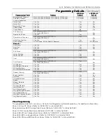
Страница 30: ...24 Hr Test UL864 Comm Fire Yes No No No Cellular Rollover Yes No Yes Yes System System System System Alarm Report Delay No delay 15 Seconds 30 Seconds 45 Seconds 30 Seconds No Delay Burglary Alarm Sound Yes No Yes Yes Daylight Savings Time Yes No Yes Yes Time Zone Offset UTC 5 00 Eastern Time US Canada UTC 5 00 Eastern Time US Canada Software Version XX XX XXXXX XXX Viewable Only XX XX XXXXX XXX X...

Страница 31: ... Yes Alarm Restore Yes No Yes Yes Alarm Cancel Yes No Yes Yes Test Not programmable LCP300 L Yes Yes No LCP300 LC Yes Test Restore Not programmable LCP300 L Yes Yes No LCP300 LC Yes Low Battery Yes No Yes Yes Low Battery Restore Yes No Yes Yes RF Low Battery Yes No Yes Yes RF Low Battery Restore Yes No Yes Yes Recent Closing Not programmable LCP300 L Yes Yes No LCP300 LC Yes Event Log Full Yes No ...

Страница 32: ...tay N A N A Button N A 146 1 Key Fob No Response N A N A Button N A 147 3 Key Fob Arm Away N A N A Button N A 148 2 Key Fob Disarm N A N A Button N A 149 4 Key Fob Arm Stay N A N A Button N A 150 1 Key Fob No Response N A N A Button N A 151 3 Key Fob Arm Away N A N A Button N A 152 2 Key Fob Disarm N A N A Button N A 153 4 Key Fob Arm Stay N A N A Button N A 154 1 Key Fob No Response N A N A Butto...

Страница 33: ...Key Key Zone Zone Zone Zone Zone 131 Zone 131 Zone 131 Zone 131 162 162 162 162 Temperature Temperature Temperature Temperature Zone Zone Zone Zone Zone 280 Zone 280 Zone 280 Zone 280 291 291 291 291 Keypad Keypad Keypad Keypad Zone Zone Zone Zone 850 850 850 850 857 857 857 857 RF Supervised Button High Temp 60Min RF Unsupervised Low Temp Arm Night Arm Night Arm Night Arm Night Activate Deactivat...

Страница 34: ...X Series Devices is displayed on the Zone Programming Screen for the individual Zone that is programmed Signal strength information is provided below Icon Icon Icon Icon Description Description Description Description Signal Strength Signal Strength Signal Strength Signal Strength Four Green Bars Greater than 27 dBm Three Green Bars Greater than 45 dBm Two Green Bars Greater than 63 dBm One Green ...

Страница 35: ...ferences nuisibles 2 Cet appareil doit accepter toute interference reçue y compris les interferences causant une reception indésirable RF Exposure Warning RF Exposure Warning RF Exposure Warning RF Exposure Warning The antenna s used for this device must be installed to provide a separation distance of at least 7 8 inches 20 cm from all persons and must not be co located or operating in conjunctio...

Страница 36: ...eams of protection and intrusion can only be detected in unobstructed areas covered by those beams They cannot detect motion or intrusion that takes place behind walls ceilings floors closed doors glass partitions glass doors or windows Mechanical tampering masking painting or spraying of any material on the mirrors windows or any part of the optical system can reduce their detection ability Passi...

Страница 37: ...r delay of alarm reporting and sounding can exceed UL Standard limits for commercial and residential applications the following requirements per UL681 are provided The maximum time that a control unit shall be programmed to delay the transmission of a signal to a remote monitoring location or to delay the energizing of a local alarm sounding device to permit the alarm system user to enter and disa...

Страница 38: ...onds and 2 3 or 4 minutes 30 seconds 30 seconds minimum Entry Delay 2 None 15 30 45 60 and 90 seconds and 2 3 or 4 minutes 30 seconds 30 seconds minimum Exit Delay 45 60 90 and 120 seconds 60 Seconds 45 seconds minimum Restart Exit Time Enabled or Disabled Yes Enabled Enabled Exit Warning Not selectable Yes Enabled Enabled Auto Stay Arming Enabled or Disabled Yes Enabled Enabled Cross Zone Delay 3...

Страница 39: ...ical Physical Dimensions 8 82 22 4cm W x 6 97 17 7cm H x 1 4 3 6cm D Electrical Electrical Electrical Electrical Voltage Input 110VAC 60 Hz 9 Vdc from plug in 2 5A power supply Rechargeable Backup Battery Nickel metal hydride battery pack rated at 7 2 Vdc LCP500 4B rated at 1100 mAh LCP500 24B rated at 3700 mAh Environmental Environmental Environmental Environmental Operating Conditions 32 122 F 0...

Страница 40: ...dio Service GSM Global System for Mobile communications which is an international standard for digital mobile phone systems used for cellular communication HSDPA High Speed Downlink Packet Access HSPA High Speed Packet Access ICCID Integrated Circuit Card Identifier SIM Card serial number IMEI International Mobile Equipment Identity number IP Internet Protocol IP Address A unique number consisting...

Страница 41: ...ck all wiring connections Determine that the power supply and or backup battery are supplying proper voltages Verify your programming information where applicable Note the proper model number of this product and the version level if known along with any documentation that came with the product Note your Honeywell customer number and or company name Having this information handy will make it easier...

Страница 42: ...Lyric Gateway Installation and Reference Guide 42 Notes Notes Notes Notes ...

Страница 43: ...Lyric Gateway Installation and Reference Guide 43 Notes Notes Notes Notes ...

Страница 44: ...Lyric Gateway Installation and Reference Guide 44 Notes Notes Notes Notes ...

Страница 45: ...Lyric Gateway Installation and Reference Guide 45 Notes Notes Notes Notes ...

Страница 46: ...Crystal Display LCD touch screen 15 Loading factory defaults 17 LYRIC 3G 10 LYRIC 3GC 10 LYRIC CDMA 10 Master code 20 Master security code 20 Master user features 16 Master user tools screen 16 Memory of alarm 20 Menu mode 14 Microswitch 27 Navigating 14 16 Navigation keys 15 Network configuration 28 29 Operator commands 23 Plug in power supply 9 Range 12 Reboot 27 Rebooting the system 27 Replacin...

Страница 47: ...E IF AN EXTERNAL CELLULAR RADIO ANTENNA IS USED THE ANTENNA MAY BE INSTALLED OR REPLACED ONLY BY A PROFESSIONAL INSTALLER LYRIC 3G 3GC THE EXTERNAL ANTENNA MUST NOT EXCEED A MAXIMUM DIRECTIONAL GAIN INCLUDING CABLE LOSS OF 6 0 DBI AT 850 MHZ AND 2 5 DBI AT 1900 MHZ UNDER NO CONDITIONS MAY AN ANTENNA GAIN BE USED THAT WOULD EXCEED THE ERP AND EIRP POWER LIMITS AS SPECIFIED IN FCC PARTS 22H 24E AND ...

Страница 48: ...latest warranty information please go to www honeywell com security hsc resources wa For patent information go to www honeywell com patents MyWebTech MyWebTech MyWebTech MyWebTech Warranty Warranty Warranty Warranty Patents Patents Patents Patents 2 Corporate Center Drive Suite 100 P O Box 9040 Melville NY 11747 Copyright 2016 Honeywell International Inc www honeywell com security Ê800 Ê800 Ê800 Ê...

Отзывы: