


General considerations
User manual for HON R100 gas pressure regulator with HON P095NG pilot
6
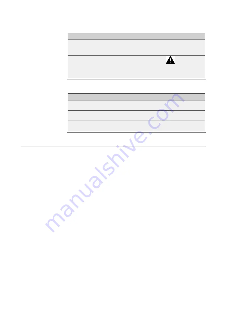
Type of safety notice
Description
Sign
Step‐related safety
notices
Safety notices containing specific instructions
relating only to the step
DANGER
WARNING
CAUTION
Additional safety
notice
Instruction to observe certain safety notices
with reference to a location in the document
where safety notices containing specific
information about dangers, risks and specific
instructions for safety procedures can be found
The safety notices containing specific instructions are identified with a signal word. The signal
word represents a certain danger level:
Danger level
If you fail to follow the instruction, then …
And the consequence is …
DANGER
an accident will happen
serious bodily injury or
death.
WARNING
an accident may happen
possible serious bodily
injury or death.
CAUTION
an accident may or will happen.
minor or moderate bodily
injury.
Warnings about possible material damages are identified with the word
Attention
in this
document.
Danger levels
Warnings about material
damages


