Page 59
1 Dec 2003
34-45-4
7
MAINTENANCE MANUAL
CAS-100 COLLISION AVOIDANCE SYSTEM
Use or disclosure of information on this page is subject to the restrictions in the proprietary notice of this document.
The Mode S transponder/TCAS control unit moves the control data to the Mode S transponder
through an ARINC 429 data link. The transponder/TCAS control unit FAIL lamp receives a
failure status discrete input from the Mode S transponder.
CTA-100( ) controls and indicators are shown in Figures 10 and 11 and are functionally given
in Tables 18 and 19.
I. TCAS and Mode S Transponder Omnidirectional Antennas
TCAS can use one omni antenna installed on the bottom of the aircraft instead of a directional
antenna. The Mode S transponder uses two omni antennas; one antenna installed on the
bottom of the aircraft and the other antenna installed on the top of the aircraft.
These omni antennas are L-band monopoles and are the same to those omni antennas used
for distance measuring equipment (DME) and ATC transponders.
The BITE circuits routinely do continuity checks on the omni antennas and their cables.
6. Operation
A. General
The data in this section gives a description of CAS-100 operation that includes:
(1) Complete Block Diagrams and Description of Input/Output Signals.
(2) TCAS Failure Monitoring.
NOTE:
All data in this manual is superseded by the latest engineering software and
hardware documentation.
B. Detailed Block Diagrams and Description of Input/Output Signals
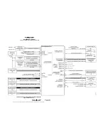
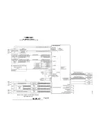
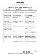
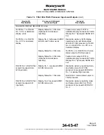
The Figure 8 is a block diagram of the CAS-100 system unit connects to the TPA-100A TCAS
Processor. The Table 10 gives the TCAS Processor input/output signals. Interwiring diagram,
Figure 2015 in the MAINTENANCE PRACTICES section, gives specified connect pin
numbers on the TCAS processor and shows the pins on the Mode S transponders and
indicators that connect to the TCAS processor.
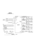
The Figure 9 is a block diagram of the system unit connects to the IVA-81A/D TA/VSI and
IVA-81B RA/VSI. The Table 11 gives the TA/VSI and RA/VSI input/output signals. Interwiring
diagram, Figure 2015 in the MAINTENANCE PRACTICES section gives specified connect pin
numbers on the TA/VSI and RA/VSI.
The total system connects for the Mode S transponder and control units are shown in the
applicable maintenance manual.
Specific connect pin numbers on the TCAS processor and a PPI or dedicated display are given
on the Interwiring diagram, Figure 2015 in the MAINTENANCE PRACTICES section. The
system connects into the optional PPI are shown in the associated maintenance manual
recorded in Table Intro-1.


