


Page 7
1 Dec 2003
34-45-4
7
MAINTENANCE MANUAL
CAS-100 COLLISION AVOIDANCE SYSTEM
Use or disclosure of information on this page is subject to the restrictions in the proprietary notice of this document.
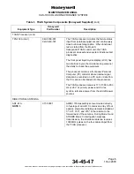
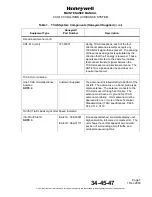
Table 1. TCAS System Components (Honeywell Supplied)
(cont)
Equipment Type
Honeywell
Part Number
Description
Directional Antenna (cont)
ANT-81A (cont)
071-50001
During TCAS receptions, each of the four
directional antenna elements accepts any
1090-MHz rf signal that is present. The phasing
of these received signals is calculated by the
direction that the rf energy is received. These
signals are directed on the same four cables
that connect transmit signals between the
TCAS processor and directional antenna. The
ANT-81A is a passive device and does not
require input power.
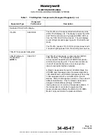
TCAS Omni Antenna
One TCAS Omnidirectional
Antenna
NOTE 2.
Customer Supplied
The antenna is installed directly to bottom of the
aircraft. The antenna is an L-band, blade type
dipole antenna. The antenna connects to the
TCAS processor through an rf cable. The
antenna must have a dc ground for TCAS
antenna monitoring. Omni antenna must be
approved to one or more of these Technical
Standard Order (TSO) specifications: C66b,
C74, C112, C119
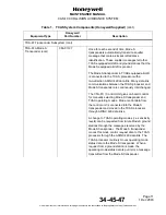
TA/VSI (Traffic Advisory/Vertical Speed Indicator)
IVA-81A/IVA-81D
NOTE 3.
IVA-81A: 066-50001
IVA-81D: 066-01171
Front-panel attached, solid-state display unit.
High-resolution, full-color, dot matrix LCD. The
unit shows the vertical speed of own aircraft,
position of surrounding aircraft traffic, and
vertical maneuvering RAs.