Page 26
1 Dec 2003
34-45-4
7
MAINTENANCE MANUAL
CAS-100 COLLISION AVOIDANCE SYSTEM
Use or disclosure of information on this page is subject to the restrictions in the proprietary notice of this document.
C. Component Leading Particulars
(1) Leading Particulars
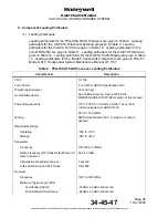
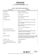
Leading particulars for the TPA-100A TCAS Processor are given in Table
8. Leading
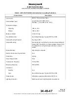
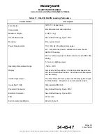
particulars for the ANT-81A Directional Antenna are given in Table
9. Leading
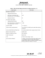
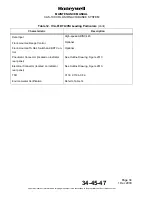
particulars for the IVA-81A TA/VSI are given in Table
10. Leading particulars for the
IVA-81B RA/VSI are given in Table
11. Leading particulars for the IVA-81D TA/VSI are
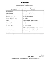
given in Table
12. Leading particulars for the ITA-81A Traffic Display are given in Table
13. Leading particulars for the Mode S transponder components are given in TRA-67
Mode S ATC Transponder System Maintenance Manual I.B. 1167.
Table 8. TPA-100A TCAS Processor, Leading Particulars
Characteristic
Description
TSO
C-119b
Form Factor
4 or 6 MCU, ARINC Specification 600
Weight (Approximate)
14 lb (6.3 kg)
Overall Dimensions
See Outline Drawing, Figure
2006 in the
MAINTENANCE PRACTICES section of this manual.
Power Requirements
115 V, 400 Hz, 110 watts and 26 V ac synchro
reference power per ARINC 413A
28 V dc 160 Watts
Cooling
ARINC Specification 600. Forced air cooling is
optional.
Temperature Range
Operating -55C
to
+70C
Storage
-55C to +85C
Transmitter
Frequency
1030.00 ± 0.01MHz
Radio Frequency (RF) Peak Output Power at
Rear Connector
54.0 ± 2 dBm
Interrogation Repetition Interval
1 second
Pulse Width, Rise and Fall Times
DO-185A
Receiver
Frequency
1087 to 1093 MHz
Minimum Trigger Level (MTL)
For Standard ACAS
-74 dBm ± 2 dBm at Antenna
For Extended Performance
-84 dBm ± 2 dBm at Antenna

