Page 51
1 Dec 2003
34-45-4
7
MAINTENANCE MANUAL
CAS-100 COLLISION AVOIDANCE SYSTEM
Use or disclosure of information on this page is subject to the restrictions in the proprietary notice of this document.
(5) Rear Connector
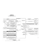
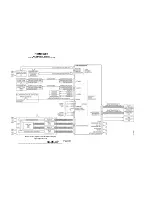
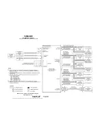
A six section rear connector supplies the system connects to the TCAS processor. The
six sections of the connector are shown left bottom plug (LBP), right bottom plug (RBP),
left middle plug (LMP), right middle plug (RMP), left top plug (LTP), and right top plug
(RTP). The Figure
8 shows the external devices connected to each of the six sections of
the connector. The system Interwiring Diagram, Figure
2015 in the Maintenance
Practices section of this manual, shows the specified pin connections into the TPA-100A
TCAS processor.
(6) Leading Particulars
TCAS processor leading particulars are given in Table
8. Refer to TPA-100A Component
Maintenance Manual for more data.
B. Directional Antenna
(1) General
The ANT-81A Directional Antenna
(Figures 2007, 2008, 2009, and 2010) lets the bearing
of intruder aircraft be determined by allowing the TCAS processor to transmit the
interrogations and receive replies on one of four antenna beams. By selecting the beam,
the TCAS processor electronically points the antenna in a surveillance direction during
TCAS transmit and receive operations.
(2) TCAS Directional Antenna Description and Basic Functions
The directional antenna is an electronically steerable phased array that has four top
loaded monopole elements.
Different from mechanically steered antennas, the antenna pattern can be pointed in one
of four directions without moving the antenna. This movement is achieved by
independently changing the drive level and phase to the four antenna elements
contained in the directional antenna.
The four beam forming elements are found on the edge of the antenna, and the full
assembly is contained in an aerodynamic fiberglass enclosure just over one inch in
height. The top directional antenna must be installed at, or near, the longitudinal
centerline of the ai 5 degrees and as far forward as practical. The bottom
directional antenna or omni antenna (if used) must be put as near as possible to the
vertical plane of the top directional antenna. During TCAS transmission, the directional
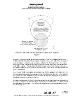
antenna (top or bottom) radiates 1030 MHz main beam patterns under control of the four
antenna element drive signals from the TPA-100A TCAS processor (see beam patterns
in Figure
7).

