


28
Mounting and Connection Instructions IDENTLOC Evaluation Unit
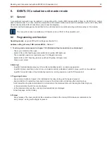
Exit teaching mode
Do not exit the teaching mode, until the
.
LEDs of all required sensors are in off-mode
Switching to normal operating state:
1.) Switch
.
S1/8 to "OFF"
2.) The EU now checks for approx.
that the data transmission of the sensors is functioning correctly. If evaluation is "OK",
1 second
the sensor code is permanently stored.
3.) After checking, the relevant sensor LED lights up for approx. 1 second if a sensor malfunctions or if no sensor is available. If the
LED of an occupied sensor lights up, repeat the teaching mode.
4.) The teaching mode is then automatically exited.
The LED "Teaching mode" (yellow) goes out. The EU is now in indication mode (normal mode).
If necessary, set the address and BUS system according to the application. Disconnect the operating voltage briefly after changing
the setting
Place cover in position
Alarm and tamper transmission is automatically stopped. If connected to the control panel, the tamper alarm remains stored until it is
cleared.
7.8.4
Data transmission in normal mode
Sensors, that were stored on exiting the teaching mode as "NOK" (not occupied or evaluated as NOK), will be handled accordingly
depending on the operating mode:
- BUS-1 in 5 address mode and BUS-2:
Transmission to the control panel "NOK" (triggered)
- BUS-1 in 1 address mode:
No transmission to the control panel
Attention!
This differs from the previous version EU BUS-1 in 5 address mode. Transmission in these cases was OK.
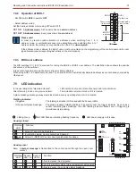
After activating the
, all connected sensors
teaching mode
are automatically registered.
The indications off-mode sensor LEDs indicate when registrati-
on is completed. If an LED of an occupied sensor is still lit up or
flashes, this indicates a fault or a triggering of the corresponding
sensor (see following table).
Such sensors are stored as
on exiting the
not available
teaching mode!
Register sensors
ON
12
ON
12
3
4
56
78
ON
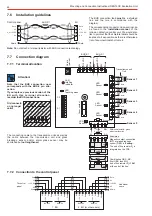
LED
totalling
indicator
LED
Teaching mode
Cover contact
LED
Sensor 1
LED
Sensor 2
LED
Sensor 3
LED
Sensor 4
LED
Sensor 5
LM
NM
Address
BUS-2
BUS-1
S1
S2
1)
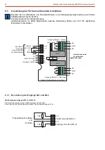
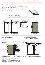
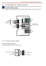
Check installation! (e.g. the distance to the mounting surface of metal, distance transmission unit
sensor etc., see
®
Chapter 6.1 in these instructions as well as the mounting and connection instructions of the relevant sensor.)
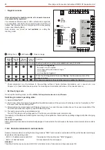
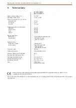
Totalling
LED
Teaching
LED
Sensor
LED 1-4
Sensor
LED 5
Teaching mode active, all sensors available and ready to funciton
If a sensor LED
lights up
- the sensor is not occupied
- or it is beyond the transmission range
1)
- or it is defect
- or it has already triggered.
When the LED allocated to the sensor
, the transmission state of the
flashes
sensor is critical
1)
No sensor connected or the end of line resistor is outisde the tolerance
LED lights up LED flashes Does not apply
off-mode
off-mode
Function