


26
Mounting and Connection Instructions IDENTLOC Evaluation Unit
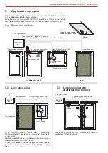
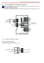
7.7.2
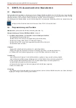
Connection to the control panel
Attention!
Note that the BUS connection now
corresponds with the BUS-2 pin allo-
cation.
If you replace a previous version of the
EU with this terminal allocation,
resolder the BUS connections.
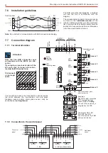
7.6
Installation guidelines
The BUS connection lead
be a shielded
must
line and the core in accordance with the
diagram.
The corresponding conductor cross-sectins can
be found in the
of the
installation manual
intrusion detection central unit. We would also
like to point out that the shield terminal should be
kept as short as possible, as there is otherwise a
risk of an uninentional short circuit.
Note:
Do not attach a terminal resistor with
connection technology.
BUS
Data
0 V
+12 V DC
0 V
Data
0 V
0 V
U_b +12 V DC
EU
BUS-2/1
Shield
Shield
Control panel
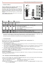
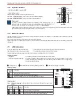
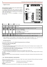
7.7
Connection diagram
7.7.1
Terminal allocation
The connecting cable to the transmission units as well as
the cable between the transmission unit and glass
breakage sensor and/or alarm glass sensor may be
shortened but
not lengthened.
ON
12
ON
12
3
4
56
78
S1
S2
free
Differential detector group
with clear function
DG
0V
Shield
terminal
LED
totalling
indicator
LED
Teaching mode
Cover contact
Transmission unit
1 to 4
R on board
A
+12V DC
Data
0V
0V
+12V DC
Data
0V
0V
BUS-2/1
BUS-2/1
O
red
white
I
O
red
white
I
O
red
white
I
O
red
white
I
Sensor 2
Sensor 1
Sensor 3
Sensor 4
LED
Sensor 1
LED
Sensor 2
LED
Sensor 3
LED
Sensor 4
Sensor 5
LED
Sensor 5
Shield
Shield
Shield
Shield
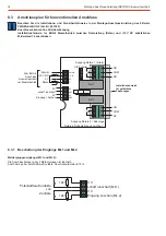
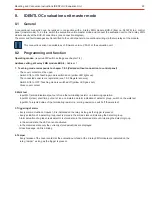
To control
panel
Additional
users
Shield
Shield
BUS-2/1
BUS-2/1
0V
0V
Data
Data
+12V DC
+12V DC
1. EU
0V
0V
BUS-2/1
BUS-2/1
0V
0V
Data
Data
+12V DC
+12V DC
2. EU (or other users)
0V
0V
0V
Data
+12V DC
Shield
0V
0V
Data
+12V DC
Shield
0V
12k1
DG
0V
GBS
MC
GBS
MC
Examples:
Magnetic contact connection
(MC) or glass breakage
sensor (GBS) in
Z wiring.
The end of line resistor R is
A
integrated on the PCB.
Combination GBS - MC.
(first GBS, then MC)
end of line resistor R =
A
12k1
at the end of the line.
12k1
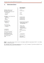
R on board
A
+12V DC
+12V DC
Data
Data
0V
0V
BUS-1
BUS-1
Old connecti-
on no longer
valid!