


25
Mounting and Connection Instructions IDENTLOC Evaluation Unit
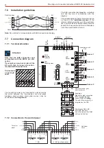
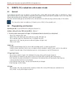
7.5
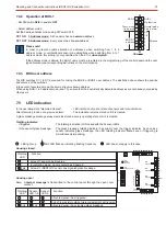
LED indication
In the operating state "disarmed cleared":
- LED indication of current state of sensors and total indication.
After disarming in case of a previous alarm:
- The indication remains stored until it is cleared.
A glass breakage message always remains stored at every operating state until it is cleared.
Totalling indicator:
- If triggered:
The totalling indication is OR-linked with the 5 sensor LEDs.
- In the event of glass breakage:
The glass breakage totalling indicator has priority over the trigger indicator. As soon as a
sensor indicates glass breakage, the LED totalling indicator flashes even if triggering is
simultaneously impending.
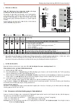
LED
Sensor 1
LED
Sensor 2
LED
Sensor 3
LED
Sensor 4
LED
Sensor 5
ON
1
2
ON
1
2
3
4
5
6
7
8
S1
S2
Cover contact
LED
totalling
indicator
LED
Teaching mode
3Hz
LED lights up
LED flashes, indicating flashing frequency LED does not apply in this case
3Hz
Function
Housing open:
Note: A
is transmitted to the control panel through the open cover
tamper message
contact.
Sensor-
LED 1-4
Sensor-
LED 5
3Hz
3Hz
Function
Totalling
LED
At least 1 sensor has triggered
In indication mode: Cover contact has triggered
At least 1 IDENTLOC sensor has signaled glass breakage
Totalling
LED
Allocated sensor has triggered
End of line resistor outside tolerance/detector has triggered
Allocated sensor has signaled glass breakage
Housing closed:
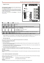
7.4.2
Operation at BUS-1
- Set DIP switch
in position
S2/2
OFF
- Select address mode:
Set the desired address mode using DIP switch S1/7:
S1/7 ON
1-Address mode:
All 5 sensors have a
address.
common
S1/7 OFF 5-Address mode:
Every sensor has its
address.
own
Please note!
In order to prevent double allocation of addresses when switching from 1 to 5
address mode- or unintentional sensor zone allocations when switching from 5 to 1
address mode, this setting iy only possible when the EU is
de-energized.
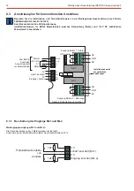
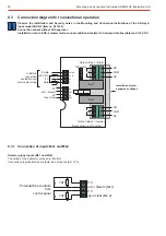
7.4.3
BUS user address
The DIP switches S1/1 to S1/6 are used for coding the BUS-2 or BUS-1 user address. The illustration above shows the position
and valence of the switches.
In the event of several users, each user must receive its own address.
When using BUS-1 in 5 address mode (see 7.3), ensure that the 4 automatically allocated addresses are not already occupied by
other users.
ON
12
ON
12
3
4
56
78
BUS-2
32
16
8
4
2
1
S1
S2
ON
BUS-1
Teach. mode
1-add. mod.
BUS-2/1
address
No function
Normal mode
5-add. mod.
Valence
If the address mode is altered, the
users must be re-entered in the programming of the
and the user
BUS-1
control panel
type allocated. (see corresponding instructions on the
).
control panel