
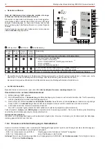


Strain relief of cables:
Before closing the housing of the EU, secure the cables using cable binders at the provided retainers.
Seal housing:
The housing of the EU should be sealed when installation has been completed correctly and the system has
been tested. Press the enclosed plastic seals into the screw opening on the front of the housing.
Clean the seal (free from grease) and cover with the label (VdS imprint).
After attaching the plastic seal, the housing can no longer be opened without destroying the seal.
6.2
Installation in compliance with VdS
Before final installation, we always recommend performing a
(in the
, see Chapter 7.8 EU BUS-
test
teaching mode
2/BUS-1). The test can be carried out with or without a connection between the EU and the
.
control panel
In order to determine the
please observe the mounting and connection instructions of the
optimum installation site,
relevant sensor.
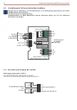
The connecting cable to the transmission units as well as the cables between the transmission unit and the glass
breakage sensor or the alarm glass sensor may be shortened but
not lengthened.
Installation in metal profiles (e.g. aluminium) is only possible with
sensors.
slimline
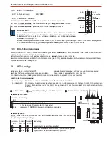
5.4
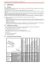
Further application possibilities
- Monitoring of art objects
(e.g. a valuable picture)
As a code carrier, an ID card, for example, is attached to the back of a picture. The transmission unit can therefore be mounted
in the wall behind the picture (invisible) or also surface-mounted.
As all IK2/proX1 code carriers
are used in conjunction with an IDENTLOC transmission unit, the application
provided by us
possibilities know no limits.
- Inductive transmission of a switching function
(without galvanic coupling)
A switching contact can be connected to the alarm glass sensor instead of the alarm glass.
A detailed description can be found in the mounting and connection instructions of the alarm glass sensor.
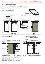
6.
Installation guidelines
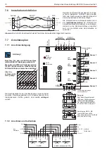
6.1
Transmission range
IDENTLOC sensors
The transmission range
depends mainly on the installation surface. Surfaces
between transmission unit and sensor element
of wood or plastic allow an optimum range. To ensure good transmission, the housing distance of both transmission elements
must be
.
2 to 5 mm
The maximum admissible distance (10 mm) should not be used if possible. Falling below 2 mm is not allowed!
For surfaces of
(steel, aluminium) the range can, under certain circumstances, be
metal
reduced considerably
In this case, the transmission unit and the sensor element must be installed must be surface mounted, e.g. the surface mounting
set,
no. 030810 can be used for this purpose.
Item
IDENTLOC
sensors
slimline
To ensure good transmission, the housing distance of both transmission elements must be
.
2 to 5 mm
The maximum admissible distance (10 mm) should not be used if possible.Falling below 2 mm is not allowed!
If this distance is not possible, both transmission units can be installed in the frame and/or the wing.
Mounting and Connection Instructions IDENTLOC Evaluation Unit
23