


Rev. 1.20
49
October 28, 2020
BC45B4523
Besides, the output driver includes the non-overlapping clock to reduce the power due to leakage current from
T_V
DD
to ground during switching. TX_EN is an internal global control signal sent from the main control block
operated in CardDetect and FieldDetect mode. When TX_EN is cleared, in FieldDetect operation, both the driver
pins, the TX1 and TX2, are configured to Hi-Z state.
TX Overshoot Control
The device provides RF overshoot protection control to avoid both overshoot and undershoot during
communication. When the TX Envelope, ENV, is toggled low, internal overshoot timer starts operation. The timing
control can be separated into several phases.
In the first phase, controlled by the TxOvsT1Fall bit field, TX output conductance is cleared when 100ASK=“1”,
or set to the value of the TxCfgMod bit field when 100ASK=“0”. Secondly, TX output conductance is defined by
the TxCfgFall bit field for a time configured by the TxOvsT2Fall bit field. Then conductance is cleared or set to
the same value of the first phase and wait until ENV is toggled high. When ENV is set high, TX conductance is
set to the value of the TxCfgCW bit field for a time configured by the TxOvsT1Rise bit field and then changed
to TxCfgRise for a time configured by the TxOvsT2Rise bit field. Finally, TX conductance will return to un-
modulation level, TxCfgCW. The TX conductance and timing of each phase is defined as listed in the following
table.
Phase
Timing Control
Address.Bit
TX
Conductance
Address.Bit
Note
1
TxOvsT1Fall
Sector1-0x10.[7:4]
0
—
100ASK=“1”
TxCfgMod
Sector0-0x13.[5:0] 100ASK=“0”
2
TxOvsT2Fall
Sector1-0x10.[3:0]
TxCfgFall
Sector1-0x12.[5:0]
—
3
Depend on ENV width
—
0
—
100ASK=“1”
—
TxCfgMod
Sector0-0x13.[5:0] 100ASK=“0”
4
TxOvsT1Rise
Sector1-0x11.[7:4]
TxCfgCW
Sector0-0x12.[5:0]
—
5
TxOvsT2Rise
Sector1-0x11.[3:0]
0
—
100ASK=“1”
TxCfgRise
Sector0-0x13.[5:0] 100ASK=“0”
TX Overshoot Control Settings
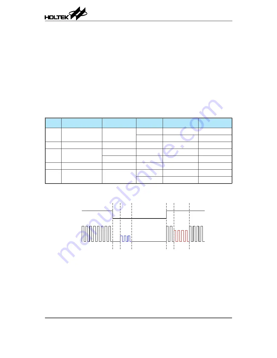
The TX overshoot control examples are shown in the fol lowing figures.
ENV
TX
Tx
Ov
sT
1Fall
TxO
vsT2Fall
Tx
Ov
sT1Rise
Tx
Ov
sT2Rise
TxCfgCW
TxCfg-
Fall
TxCfgRise
TxCfgCW
TX Example Waveform for Overshoot Control
(100ASK=1, TxOvsT1Fall=2, TxOvsT2Fall=3, TxOvsT1Rise=2, TxOvsT2Rise=4)