HOLEMAKER Pro 35 Auto Скачать руководство пользователя страница 6

6

GENERAL INFORMATION

The PRO 35 AUTO is supplied in a metal box with complete standard equipment. 

The included equipment consists of:

•  1x Drilling machine

•  1x Metal box

•  2x Spoke handle

•  1x Cooling system bottle

•  1x Chip guard

•  1x Safety strap

•  1x 4mm hex wrench

•  1x Operator’s manual
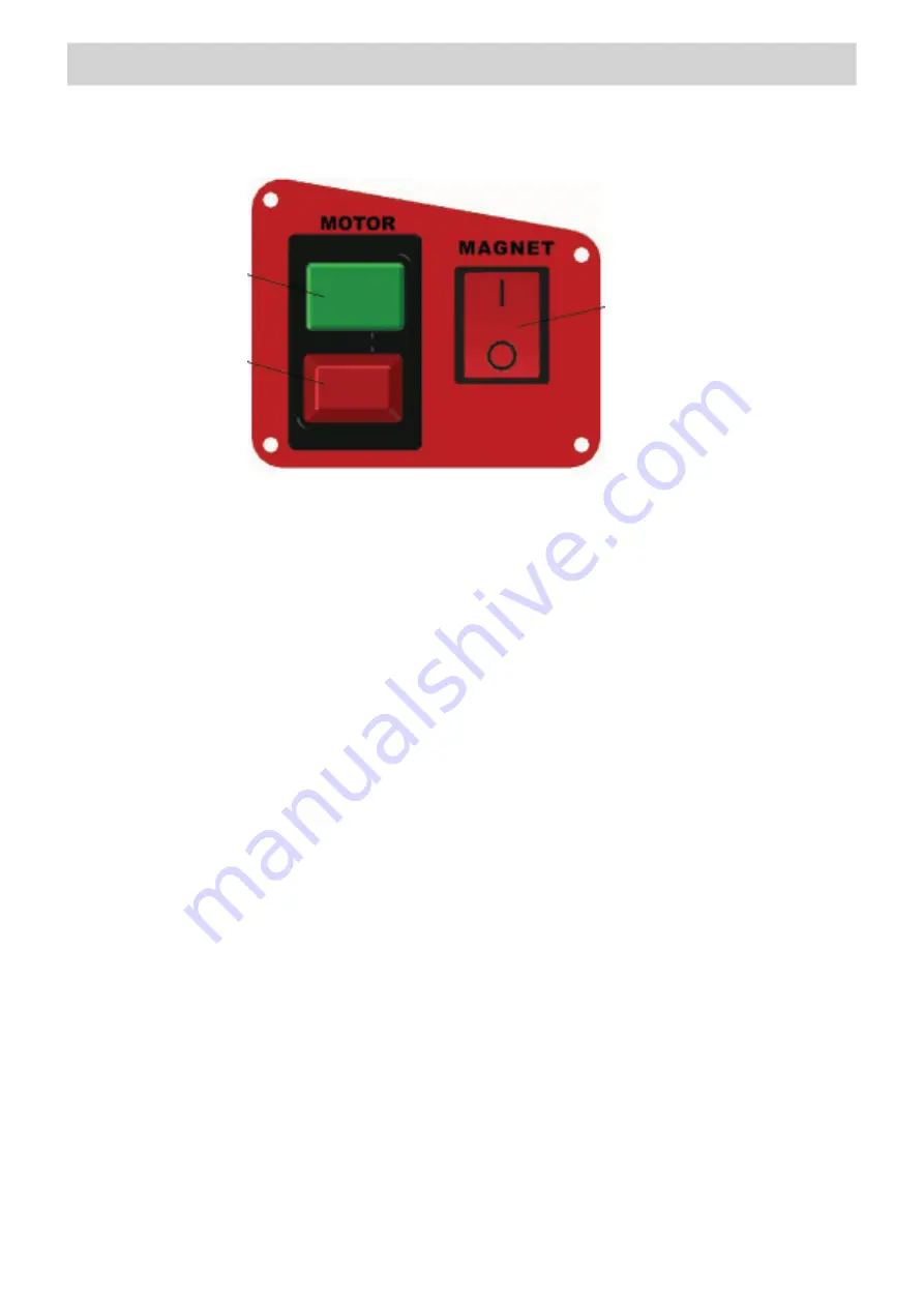
Figure 2.

 Control panel design

1.4. Equipemnt included

Motor START button

Motor STOP button

Electromagnetic 

base ON/OFF switch

2. Safety instructions 

1.  Before beginning, read this Operator’s Manual and complete proper occupational health 

and safety training.

2.  The machine must be used only in applications specified in this Operator’s Manual.

3.  The machine must be complete and all parts must be genuine and fully operational.

4.  The electrical supply specifications must conform to those specified on the rating plate.

5.  The machine must be plugged into a properly grounded (earthed) socket-outlet. The 

electrical supply must be protected with a 16 A fuse for 230 V. When used on building 

sites, supply the machine through an isolation transformer made with class II protection 

only.

6.  Never carry the machine by the cord or pull it to disconnect the plug from the power 

outlet as this may damage the power cord and result in electric shock.

7.  Transport and position the machine using the carrying handle, with the magnet switch 

set to position ‘O’ (off).

Содержание Pro 35 Auto

Страница 1: ...URE EVERYONE USING THIS MACHINE READS AND UNDERSTANDS ALL SAFETY AND OPERATING INSTRUCTIONS IN THIS MANUAL Serial Date of Purchase Ver 1 1 07 10 2015 OPERATOR S MANUAL PART HMPRO35AUTO PRO 35 AUTO DRI...

Страница 2: ...is not a result of normal wear and tear Written permission has been received from ITM prior to commencement of repair Repairs tampering or modification carried out by unauthorised personnel will void...

Страница 3: ...3 Design 5 1 4 Equipment included 6 2 SAFETY INSTRUCTIONS 6 3 START UP AND OPERATION 8 3 1 Mounting and operating the annular cutter 8 3 2 Mounting and dismounting the cooling system bottle 10 3 3 Con...

Страница 4: ...ned to drill holes with diameters of 12 36 mm 0 47 1 42 to the maximum depth of 51 mm 2 through the use of annular cutters The electromagnetic base allows the drilling machine to be fixed to ferromagn...

Страница 5: ...the tip of the pilot pin above the drilling point Figure 8 Configuration of the spoke handles manual feed a automatic feed b PRO 36 AUTO Operator s Manual a b The cooling system works by means of gra...

Страница 6: ...only in applications specified in this Operator s Manual 3 The machine must be complete and all parts must be genuine and fully operational 4 The electrical supply specifications must conform to thos...

Страница 7: ...he front 21 Before every use inspect the machine to ensure it is not damaged Check whether any part is cracked or improperly fitted Make sure to maintain proper conditions that may affect the operatio...

Страница 8: ...wear protective gloves and place the cutter into the arbor 3 in such a way to align the flats 4 with the set screws 5 Finally tighten both set screws with the supplied 4 mm hex wrench To remove the c...

Страница 9: ...with annular cutters PRO 36 AUTO Operator s Manual incomplete through holes complete through holes slug core spring pilot pin annular cutter arbor 9 Figure 4 shows how annular cutters operate As the...

Страница 10: ...tem bottle on the screws 1 Figure 6 and attach the bottle hose to the coupling 2 Dismount in reverse order 3 3 Control system of the electromagnetic base holding force The PRO 35 AUTO drilling machine...

Страница 11: ...must be clean without rust or paint that decrease the holding force of the electromagnetic base Then connect the drilling machine to the power outlet and enable the holding force of the electromagnet...

Страница 12: ...drilling oil is also satisfactory To check the operation of the cooling system slightly loosen the bottle cap open the valve using the lever and initially apply pressure on the pilot pin by rotating t...

Страница 13: ...elled from the tool with a significant force 3 5 Drilling Start the motor by pressing the green MOTOR button Slowly rotate the spoke handles counterclockwise to bring the cutter close to the workpiece...

Страница 14: ...verse order After the replacement run the motor without load for 20 minutes 3 6 Replacing the motor brushes Check the condition of the carbon brushes every 100 operational hours If the length of the b...

Страница 15: ...15 NOTES...

Страница 16: ...Steel Multi Cut Geometry 12 to 32mm Metric 25mm 50mm Stainless Steel Cast Iron Super Cut M42 Cobalt M42 High Speed Steel 8 Cobalt Titanium Nitride Coated Made In U S A Multi Cut Geometry 1 2 to 1 Impe...

Отзывы: