background image

25

monty 3550

2.3.2   Instalación del Kit: EAA0304G80A - KIT 
DE CAMBIO RÁPIDO PARA HERRAMIENTA 
CON EXTENSIÓN DE +4”

ADVERTENCIA
ANTES  DE  LA  INSTALACIÓN,  DESCONECTE  LA 
DESMONTADORA  DE  NEUMÁTICOS  DE  LOS 
SUMINISTROS DE ELECTRICIDAD Y AIRE COMPRIMIDO.

Operaciones preliminares

Véase la 

Figura 2.3.2-1

1) Quite los dos tornillos (

A

) de la herramienta acoplada 

en la desmontadora de neumáticos.
2) Desenrosque y quite el tornillo de fi jación (

B

) debajo 

de la herramienta.
3) Si la desmontadora de neumáticos tiene una palanca 
mecánica para la barra hexagonal, utilice la palanca para 
bloquear la varilla. Memorice la posición de la herramienta, 
después sáquela de la barra hexagonal.

NOTA

: La barra hexagonal debe retraerse a mano para 

evitar que el resorte vertical la empuje hacia arriba.

Instalación del kit

Véase la 

Figura 2.3.2-2

4) Introduzca la virola roscada (

C

), la arandela 41x53x2 

(

D

) y ponga el buje de conexión (

E

) en la barra hexagonal, 

colocada de manera que los agujeros de los tornillos del 
ajustador  miren  hacia  arriba  y  estén  alineados  con  los 
agujeros en la barra.
5)  Enrosque  el  tornillo  10x20  (

G

)  a  mano,  sin  apretar, 

acoplando también la arandela 10x32 (

H

).

6) Enrosque los dos tornillos (

F

) suministrados en el kit 

con la misma fuerza, sin apretar, de manera que el buje 
permanezca centrado.
7) Apriete los tornillos (

F

) completamente, apretándolos 

poco  a  poco  en  turnos,  después  acabe  de  apretar  el 
tornillo situado debajo (

G

).

Instalación de la herramienta suministrada en el kit

Véase la 

Figura 2.3.2-3

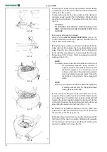
8) Acople la herramienta suministrada en el kit (

L

) en la 

conexión rápida para la extensión, colocada de manera 
que  los  tornillos  de  ajuste  (

M

)  están  alineados  con  los 

asientos (

N

) en el buje de la conexión.

9)  Enrosque  los  tornillos  (

M

)  en  la  herramienta  con  la 

misma fuerza, sin apretar a fondo.
10) Enrosque el tornillo 10x30 (

S

) con la arandela 10x38 

(

R

) a mano, sin apretar completamente.

11) Acople  el  conjunto  formado  tal  y  como  se  describe 
en el buje anteriormente acoplado. Apriete la virola con 
la llave que se incluye en el kit (

Q

).

Nota: Sitúe la herramienta en la misma posición que la 
original extraída de la desmontadora de neumáticos.

2.3.2      Montage  du  Kit:  EAA0304G80A  -  KIT 
CHANGEMENT RAPIDE OUTIL A EXT4”

AVERTISSEMENT ! 
AVANT L’INSTALLATION, COUPEZ L’ALIMENTATION 
ELECTRIQUE ET PNEUMATIQUE DU DEMONTE-PNEU

Opérations préliminaires

Voir 

Figure 2.3.2-1

1)  Dévissez  les  deux  vis  (

A

)  de  l’outil  situées  sur 

ledémonte-pneu.
2) Dévissez et ôtez la vis de fi xation (

B

) située sousl’outil.

3) Si le démonte-pneu est équipé d’un levier mécanique 
deblocage de la barre hexagonale, actionnez le levier 
pour effectuerle blocage.  Mémorisez l’orientation de 
l’outil puis retirez-le dela barre hexagonale.

N.B.

: En cas de démonte-pneu avec blocage pneumatique,il 

faudra  retenir  manuellement  la  barrehexagonale,  pour 
empêcher que le ressort vertical la fasse sortir par le haut.

Montage du Kit

Voir 

Figure 2.3.2-2

4) Mettre la bague fi letée (

C

), la rondelle  41x53x2 (

D

et montez la douille de fi xation (

E

) sur la barre hex-

agonale en l’orientant de façon à ce que les alésages 
des  vis  de  réglage  soient  en  haut  et  correspondent 
aux creux sur la barre.
5) Vissez manuellement, mais sans la serrer à fond, la vis 
10x20 (

G

), en interposant la rondelle 10x32 (

H

).

6) Vissez de la même façon, sans serrer à fond, les 
deux vis (

F

) fournies dans le kit de façon à maintenir 

le centrage de la douille.
7) Vissez à fond d’abord les vis (

F

), progressivement tour 

à tour, puis vissez en dernier la vis située en dessous 
(

G

).

Montage de l’outil fourni dans le kit

Voir 

Figure 2.3.2-3

8) Montez l’outil fourni dans le kit (

L

) sur le raccord 

rapide pour extension, orienté de sorte que les vis de 
réglage (

M

) correspondent aux logements (

N

) sur le 

moyeu de l’attelage.
9) Vissez, sans serrer à fond, les vis (

M

), situées sur 

l’outil.
10)  Vissez  manuellement,  mais  sans  forcer,  la  vis 
10x30 (

S

) avec la rondelle 10x38 (

R

).

11) Puis montez le groupe ainsi composé, sur la douille 
installée précédemment. Fermez la bague fi letée de 
blocage avec la clé fournie dans le kit (

Q

).

N.B.:

 Respectez l’orientation de l’outil qui était monté à 

l’origine sur le démonte-pneu.

Содержание monty 3550

Страница 1: ...ty 3550 Operation manual Mode d emploi Manual de Operador Electric pmeumatic pmeumatic tire changer Démonte pneus électro pneumatique pneumatique Desmontadora de neumáticos electrónica neumática neumática ...

Страница 2: ...hnician s responsibility to be knowl edgeable of the wheels and tires being changed It is essential to use proper service methods and change tires in an appropriate and acceptable manner that does not endanger your safety the safety of others in the work area or the equip ment or vehicle being serviced It is assumed that prior to using the monty 3550 Tire Changers the oper ator has a thorough unde...

Страница 3: ...IONS DE SÉCURITÉ Pour votre sécurité avant d actionner le démonte pneu monty 3550 lire complètement le présent manuel Le démonte pneu électro pneumatique monty 3550 est destinée à des techniciens spécialisés en appareils d entretien automobile et formé de façon appropriée Les consignes de sécurité présentes dans cette section et dans tout le manuel sont un aide mémoire pour l opérateur pour qu il ...

Страница 4: ...16 1 5 General Cautions Page 18 1 5 1 Precautions Page 18 2 0 Installation Page 20 2 1 Electrical Installation Page 20 2 2 Air Installation Page 22 2 3 Accessories Installation Page 22 2 3 1 Installing the Kit SLIDING JAW 4 INCH Page 22 2 3 2 RAPID CHANGE OVER TOOL EXTENSION Page 24 3 0 Controls Page 28 4 0 Mounting And Demounting Precautions Page 32 4 1 Demounting Tubeless Tires Page 32 4 1 1 Use...

Страница 5: ... de démolition Page 49 ÍNDICE DE CONTENIDOS INFORMACIÓN DE SEGURIDAD Página 7 1 0 Introducción Página 15 1 1 Nomenclatura Página 15 1 2 Características técnicas Página 17 1 3 Dimensiones de la máquina Página 17 1 4 Accesorios Página 17 1 5 Precauciones generales Página 19 1 5 1 Precauciones Página 19 2 0 Procedimiento de Instalación Página 21 2 1 Conexión eléctrica Página 21 2 2 Conexión neumática...

Страница 6: ...To reduce the risk of fire do not operate equip ment in the vicinity of open containers of flam mable liquids gasoline 6 Keep hair loose fitting clothing fingers and all parts of the body away from moving parts 7 Adequate ventilation should be provided when working on operating internal combustion engi nes 8 To reduce the risk of electric shock do not use on wet surfaces or expose to rain 9 Do not ham...

Страница 7: ...SIGNES DE SÉCURITÉ IM PORTANTES Toujours suivre les précautions de sécurité de base pendant l utilisation de cet équipement Cel les ci comprennent les démarches suivantes 1 Lire toutes les instructions 2 Ne pas utiliser un appareil endommagé ou avec un cordon d alimentation endommagé Attendre l inspection d un technicien de service autorisé et qualifié avant d utiliser l appareil 3 Si une rallonge ...

Страница 8: ... inflation cage designed for this purpose Lock turntable Clamp on inside of rim before attempting to inflate tire Use approved tire bead lubricant before removing or installing tire on rim ALWAYS position the Safety Restraint Arm over the wheel to hold it to the turntable while inflating if so equipped If a tire explodes on this tire changer STOP using it until the Safety Restraint Arm has been repla...

Страница 9: ... debe anclarse al suelo La explosión de un neumático puede causar lesiones graves Il n est pas possible d utiliser ensemble des pneus et des jantes de diamètre différent Ne JAMAIS essayer de monter ou de gonfler un pneu et une jante de diamètre différent S assurer TOUJOURS que les diamètres du pneu et de la jante correspondent bien L utilisation d un pneu et d une jante de diamètre différent pourra...

Страница 10: ... Risk of crushing Become familiar with all controls before proceeding with operation Stand away from the bead breaker arm when in operation Apply air to breaker in bursts if necessary to control arm depth Don t allow to approach extraneous people to the service Contact with moving parts could cause injury Risk of pinching or crushing hands and fingers Keep hands and fingers clear of rim edge during ...

Страница 11: ...outil de décollage pendant le fonctionnement Appliquer l air sur l outil de décollage par à coups si nécessaire pour contrôler la profondeur du bras Empêcher les personnes étrangères au service de s approcher du démonte pneu Le contact avec des parties en mouvement peut causer un accident Risque de pincement ou d écrasement des mains et des doigts Garder les mains et les doigts à distance de sécur...

Страница 12: ...e utilizar el equipo Mantenerse a distancia del brazo destalonador cuando está en marcha Si es necesario suministrar aire al destalonador de manera discontinua para controlar la profundidad del brazo No permitir que personas ajenas se acerquen al equipo El contacto con partes móviles puede provocar lesiones Riesgo de atrapamiento o aplastamiento de manos y dedos Mantener manos y dedos alejados del...

Страница 13: ...13 B L A N K P A G E monty 3550 ...

Страница 14: ...IS MANUAL INASAFE PLACE FOR FUTURE REFERENCE READ THIS MANUAL THOROUGHLY BEFORE USING THE MACHINE 1 1 Nomenclature Before installing and using the electric air tire changer it is suggested that you become familiar with the nomenclature of the machine s components Fig 1 1 1 1 Vertical slide 2 Mounting arm horizontally displaceable 3 Lever with push button 4 Handle 5 Mount demount tool 6 Tower or co...

Страница 15: ...destalonador 21 Herramienta destalonadora 22 Rodillo inferior del talón TODAS LAS OPERACIONES EN LA INSTALACIÓN ELÉCTRICATIENEN QUE SER EFECTUADAS POR PERSONAL PROFESIONALMENTE EXPERTO TODAS LAS REPARACIONES DEBEN SER EFECTUADAS POR TÉCNICOS AUTORIZADOS 1 0 Introduction Félicitations pour avoir acheté le démonte pneu électro pneumatique monty 3550 Cet ensemble de caractéristiques signifie pour votr...

Страница 16: ...s 10 25 1 3 Dimensions of the Machine Fig 1 3 1 Maximum dimensions H x D x W expressed in mm and inches H max 1860 73 D max 1920 76 W max 1720 68 1 4 Accessories Fig 1 4 1 A series of accessories are normally available for the machine All the accessories are indicated on the website http service snapon equipment net After accessing the website proceed as follows Figure 3 1 Select Accessory Plan 1 ...

Страница 17: ... la lista Introducir SEARCH 5 para visualizar la lista de los accesorios disponibles 1 2 Caractéristiques techniques Démonte pneus électro pneuma tique pour roues de voiture de fourgon et de moto avec pneus montés sur jantes à base creuse Poids lbs 740 335 kg Pression air comprimé psi 110 170 8 12 bar Force détalonneur lbs 3300 15 kN Moteur 115 VAC kW 0 75 1 Hp Couple maximum 740 ftxlbs 1000 Nm Di...

Страница 18: ...INVITE ACCIDENTS H AVOID DANGEROUS ENVIRONMENTS DON T USE POWER TOOLS OR ELECTRICAL EQUIPMENT IN DAMP OR WET LOCATIONS OR EXPOSE THEM TO RAIN J KEEP THE WORK AREA WELL LIGHTED 1 5 1 Precautions THE USE OF THIS DEVICE IS ALLOWED ONLY TO PERSONNEL DULY TRAINED BY AN AUTHORIZED HOFMANN DEALER ANY MISUSE OR MODIFICATION OF THIS DEVICE OR OF ITS PARTS OR COMPONENTS NOT PREVIOUSLYAUTHORIZED BY THE MANUF...

Страница 19: ...ESYLLAMEALSERVICIODE ASISTENCIA HOFMANN DEL REVENDEDOR AUTORIZADO 1 5 Précautions générales A PENDANT L UTILISATION ET L ENTRETIEN DE LA MACHINE IL EST IMPÉRATIF DE RESPECTER TOUTES LES LOIS ET LES RÈGLES POUR LA PRÉVENTION DES ACCIDENTS B LA LIGNE D ALIMENTATION ELECTRIQUE DOIT AVOIR UNE MISE A LA TERRE ET LE CABLE DE TERRE DE LA MACHINE JAUNE ET VERT DOIT ETRE BRANCHE AU CABLE DE TERRE DE LA LIG...

Страница 20: ...h the holes provided in the cabinet Expansion screws 12x120mm shall be used Drill 12mm holes in the floor flush with the holes provided in the cabinet Place the nogs into the holes drilled in the floor and move the machine so that the holes of the cabinet are flush with the holes in the floor Tighten the screws at 70 Nm 51 ftxlb 2 1 Electrical Installation WARNING ALL ELECTRICAL CONNECTIONS SHALL BE PE...

Страница 21: ...O SON CORRECTOS ESTO SUPONE UN RIESGO DE DESCARGA PARA EL OPERADOR 2 0 Montage et mise en oeuvre Installer la machine dans un lieu couvert et sec La température de service est de 41 122 F 5 50 C La machine peut fonctionner au dessous de 32 F mais cela exige quelques petites modifications Contactez votre distributeur Hofmann pour de plus amples informations A Enlever les vis qui fixent la machine à l...

Страница 22: ...LEFT ON THE TURNTABLE AREA TOOLS B Should you install any optional accessories please refer to the relevant instructions 2 3 Accessories Installation 2 3 1 Installing the Kit EAA0332G91A SLIDING JAW 4 INCH KIT WARNING BEFORE INSTALLATION DISCONNECT THE TIRE CHANGER FROM THE ELECTRICITY AND COMPRESSED AIR SUPPLIES See Figure 2 3 1 1 1 Remove the standard jaws R present on the tire changer turntable...

Страница 23: ...troduciendo una broca en espiral de 8 mm en los mismos varias veces ATENCIÓN DESPUÉS DE LA INSTALACIÓN LAS GARRAS DEBEN SER EQUIDISTANTES RESPECTO AL CENTRO DE LA MESA GIRATORIA 2 2 Branchement pneumatique AVERTISSEMENT L INSTALLATION PNEUMATIQUE DOIT ÊTRE EFFECTUÉE PAR DU PERSONNEL PROFESSIONNELLEMENT QUALIFIÉ AVERTISSEMENT UNE PRESSION PNEUMATIQUE EXCESSIVE PEUT COMPROMETTRE LA SECURITE DU PERSO...

Страница 24: ... positioned so that the holes for the adjuster screws are facing upward and in line with the holes in the rod 5 Screw in the screw 10x20 G by hand without tightening also fitting the washer 10x32 H 6 Screw in the two screws F supplied in the kit by the same amount without tightening so that the bush remains centred 7 Tighten the screws F fully tightening them by small amounts in turn then to conclu...

Страница 25: ... el buje anteriormente acoplado Apriete la virola con la llave que se incluye en el kit Q Nota Sitúe la herramienta en la misma posición que la original extraída de la desmontadora de neumáticos 2 3 2 Montage du Kit EAA0304G80A KIT CHANGEMENTRAPIDEOUTILAEXTENSION 4 AVERTISSEMENT AVANT L INSTALLATION COUPEZ L ALIMENTATION ELECTRIQUE ET PNEUMATIQUE DU DEMONTE PNEU Opérations préliminaires Voir Figur...

Страница 26: ...position Move the tool away from the edge of the rim then tighten the screw S under the tool with a torque of 35 Nm Installing and Adjusting the original tire changer tool See Figure 2 3 2 5 18 Fix the tool previously removed from the tire changer onto the second snap connection P2 supplied with the kit Repeat the installation operations in points 8 to 11 of these instructions 19 Adjust as already...

Страница 27: ... sustituirla rápidamente con la herramienta con una extensión de 4 pulgadas La herramienta de cambio es extremadamente rápida y le permite trabajar en llantas con un diámetro de hasta cuatro pulgadas más grandes que el máximo permitido en la desmontadora de neumáticos Réglage de l outil Voir Figure 2 3 2 4 Après avoir monté l outil sur le raccord rapide un réglage est nécessaire A l aide des deux ...

Страница 28: ...old WITH RIGHT FOOT the first pedal from the right the turntable turns clockwise Lift the pedal and the turntable turns counter clockwise D Open the bead breaker arm Press down and hold WITH RIGHT FOOT the second pedal from the right by doing this you operate the bead breaker blade and the arm will move towards the machine Release the pedal the bead breaker blade will retract E The push button on t...

Страница 29: ...priete el pedal del entalonador hinchador situado en la parte izquierda de la máquina 1 Fig 3 0 3 el aire solo llegará desde el extremo del tubo de hinchado 3 0 Commandes Avant de travailler avec la machine s assurer d avoir bien compris la position et les fonctions des commandes Fig3 0 1 A Appuyer et lâcher DU PIED GAUCHE la première pédale de gauche la potence se déplace en arrière Appuyer de no...

Страница 30: ...EXPLOSION Note For safety reasons a quick inflating valve preset to 4 5 bar is fitted upstream of the pressure gauge for the pedal operated inflating device Presetting of clamping jaws H The turntable jaws can be positioned in two different way Push the lever C on the left side of each jaw and shift at the same each one 0 4 Fig 3 0 4 N B Turntable capacity can be changed before pedal control VERY IMP...

Страница 31: ...las garras el diámetro está precon figurado directamente 1 Fig 3 0 4 En la posición 2 2 Fig 3 0 4 deben añadirse 4 al diámetro Dans le modèle avec talloneur pour tubeless F1 Appuyer sur la pédale du gonfleur 1 Fig 3 0 3 jusqu à mi course l air sort seulement de l extrémité du tuyau de gonflage 2 Fig 3 0 3 F2 Appuyer sur la pédale du gonfleur en bout de course pour actionner les jets d air des extrémit...

Страница 32: ...THE TIRE IS THE CORRECT SIZE FOR THE RIM 4 1 Demounting Tubeless Tires A Remove all wheel weights from the rim Remove the valve stem or core and deflate the tire Fig 4 1 1 NOTE If the tire is over 13 340 mm wide first set the bead breaker in the Wide position as follow 1 Pull up and hold pin 1 Fig 4 1 2 and pull the bead breaker assembly in the Wide position 2 Release pin 1 Fig 4 1 2 in its hole to ...

Страница 33: ... CON EL SENSOR DE PRESIÓN BAJA OPCIONAL INSTALADO DESTALONE CON UNA SEPARACIÓN DE 90 GRADOS DELVÁSTAGO DE LAVÁLVULA NO HAY OTROS PUNTOS EN ESTE DE DESMONTAR PARA EVITAR DAÑOS A LA RUEDA 4 0 Montage et démontage pneus précautions générales IMPORTANT AVANT DE MONTER UN PNEU SUR UNE JANTE SUIVRE LES INDICATIONS SUIVANTES A LAJANTE DOIT ÊTRE PROPRE ET EN BON ETAT SI NÉCESSAIRE LA NETTOYER ET LA PEINDR...

Страница 34: ...4 1 5 NOTE The plastic insert inside the mount demount tool must be periodically replaced Every machine is equipped with several plastic inserts inside standard equipment box If desired a steel roller also included in the standard equipment box may replace the plastic insert Follow the instructions included with the replacement parts NOTE Once the mount demount head is positioned properly matching...

Страница 35: ...ión diametralmente opuesta a la de la herramienta para mantener el talón en el canal Fig 4 1 8 Desplazar el brazo oscilante lateralmente y sacar el neumático C Positionner les griffes d une façon convenable griffes fermées pour bloquer la roue par l intérieur et griffes ouvertes pour bloquer la roue par l extérieur Quand on bloque de l extérieur des roues positionner les griffes à un diamètre proc...

Страница 36: ... the tire bar Fig 4 1 1 3 Move the roller to rest position To facilitate the lift of the bead on the head tool position the lower disk next to the edge of the lower rim edge hold firmly the arm of the disk and start the lifting of the device Fig 4 1 1 4 Demount the first bead as described in the tire changer operator s manual C Position the lower disk next to the lower rim edge Hold firmly the handle...

Страница 37: ...o fuera del centro cuando se gira EL DISPOSITIVO DEL DISCO INFERIOR NO PUEDE USARSE POR RAZONES DE SEGURIDAD 4 1 1 Utilisation du presse talon pendant la phase de démontage A Afin de faciliter le bloquage des roues avec pneus durs ou rabaissés on pourrait utiliser le presse jante du presse talon Appliquer le presse jante pos 1 Fig 4 1 1 1 sur l outil presse talon pos 2 le positionner au centre de l...

Страница 38: ...t tool is in the working position Engage the lower bead OVER the mounting wing and UNDER the mounting finger of the mounting tool Turn the wheel clockwise and push the tire down into the drop center opposite to the mount demount head Fig 4 2 3 C Mount the upper bead following the directions in section B Fig 4 2 4 With low profile tires the pneumatic bead holding and mounting tool Easymont Pro option...

Страница 39: ...co ayude a mantener el talón en el canal Fig 4 2 4 La herramienta del dispositivo de empuje el talón sigue la rotación del neumático durante la operación de montaje Vuelva a poner el rodillo y la herramienta del dispositivo de empuje el talón de nuevo en posición de reposo 4 2 Montage pneus sans chambre tubeless A Lubrifier toute la surface de la jante Fig 4 2 1 Lubrifier les deux talons du pneu à l...

Страница 40: ...THE READING ON THE PRESSURE GAUGE IS ZERO WHEN IT IS NOT IN USE THE COMPLETE SEATING THE BEAD ON THE RIM ISA VERY DANGEROUS STAGE OF THE TIRE MOUNTING PROCEDURE TO COMPLETE THE BEADING OPERATION AND INFLATE THE TIRE CORRECTLY PLACE IT IN AN AP PROPRIATE TYPE APPROVED CAGE ATIRE BURST WHATEVER ITS CAUSE CAN RESULT IN SERIOUS INJURY OR DEATH AVOID MOUNTING TIRES THAT ARE 1 2 SMALLER IN DIAMETER THAN...

Страница 41: ...tar en posición vertical mientras se procede con la introducción del aire con el Pedal o la Pistola Fig 4 3 1 4 3 Enjantage du talon des pneus Par enjantage du talon on entend l adhérence intiale du talon du pneu à la jante de manière à permettre la suite des opérations à savoir le gonflage et une parfaite pénétration du talon dans le logement de la jante Consignes de sécurité ATTENTION NE PAS UTIL...

Страница 42: ...PRESSED AIR AS SOON AS THE BEADS GRIP THE RIM WELL Place the wheel in a type approved cage to finish inflating and completely settle the beads in their seats on the rim Figure 4 3 3 WARNING WHEN OPERATING THE BEADING DEVICE IT IS COMPULSORY TO WEAR EAR DEFENDERS TO PROTECTAGAINST NOISE AND SAFETY GOGGLES TO PREVENT ANY CONTAMINATION BY DUST AND OTHER IMPURITIES BLOWN BY THE AIR JETS 4 4 Mounting and...

Страница 43: ...stalonado de montaje y desmontaje es la misma que para los neumáticos de automóviles NOTA Si es difícil montar el talón del neumático superior consulte el párrafo 4 2 1 ADVERTENCIA LAS LLANTAS SIEMPRE TIENEN QUE ESTAR BLOQUEADAS DESDE AFUERA Enjantage talon avec dispositif GP La machine peut être équipée d un dispositif GP néces saire pour le montage des pneus tubeless sur jante Fig 4 3 2 Bloquer ...

Страница 44: ...er demounting the first bead remove the tube before demounting the second bead as described in section 4 1 5 1 Mounting tube type tires A Proceed as described in section 4 2 A Do NOT lubricate the tube Talc can be used to assist with the tube positioning B Mount the valve core and place the tube onto the tire to confirm that the tube is of the correct size Fig 5 1 1 C Inflate the tube slightly if hel...

Страница 45: ...entre la cámara y el neumático Fig 5 2 1 Controlar que el neumático esté bien centrado sobre la llanta y completar el hinchado como se describe en la sección 4 3 5 0Démontagepneusavecchambre A Pour le démontage opérer comme décrit pour les pneus sans chambre au 4 1 A to 4 1 F Dans ce cas la vanne ne peut pas être remplacée car elle est unie à la chambre à air AVERTISSEMENT NE PAS ENDOMMAGER LA CHA...

Страница 46: ... wash all plastic parts with cold water and soap or window cleaner G Check the bead breaker pads Replace if worn H Discharge the water every day from air filter I The machine is equipped with an automatic lubricator Check the oil level weekly Fig 6 0 3 When adding oil to the lubricator disconnect the air supply first remove the fill screw A and add oil as needed Make sure seals are in place when repo...

Страница 47: ...o lubricador WHITE MINERAL OIL 15 cSt TAMOIL WHITE MINERAL OIL 15 SHELL ONDINA OIL 15 BP ENERGOL WT 3 TOTAL LOBELIA SB 15 ESSO MARCOL 82 6 0 Entretien AVERTISSEMENT AVANT DE COMMENCER TOUTE OPÉRATION D ENTRETIEN ET DE RÉPARATION DÉBRANCHER LA MACHINE DU RÉSEAU ÉLECTRIQUE ET DE L AIR COMPRIMÉ A Nettoyer périodiquement la tige hexagonale avec un détergent liquide non inflammable Lubrifier avec de l hu...

Страница 48: ...sal at the end of the lifetime of this equipment you must 1 Render the machine inoperative remove the plug and cut off the power supply cable close to where it comes out of the machine 2 DO NOT dispose of the equipment as urban waste and recycle it by taking the materials to suitable recycling centres 3 Contact the reseller for the closest authorised recycling centres for the disposal or for the c...

Страница 49: ...sonas La eliminación irregular implica sanciones administrativas para los infractores 7 0 VENTE Pour la mise à la décharge de l équipement arrivé en fin de vie contacter le revendeur pour une offre ou pour connaître les instructions utiles à son démantèlement Ce symbole indique l obligation d effectuer le tri sélectif des appareils électriques et électroniques au moment de sa mise à la décharge 7 1...

Страница 50: ...50 monty 3550 Notes Blank Page for Blank Page pour ...

Страница 51: ...51 monty 3550 Notes Blank Page for Blank Page pour ...

Страница 52: ...his document is subject to change without notice Snap on Equipment makes no warranty with regard to present documentation Snap on Equipment shall not be liable for errors contained herein or for incidental consequential damages in connection with furnishings performance or use of this material 309 Exchange Ave Conway AR 72032 Ph 501 450 1500 Fax 501 450 2085 Manufacturing Facilities Snap on Equipm...

Отзывы: