


17
Instruction Manual
MORSØ Notch Cutting Machine
Model NXLEH
In General
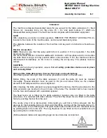
The machine is delivered assembled ready for use except for the table extensions (1), fixed
fences (2), moveable fence (4), flip stops (5) + (6), and push buttons (7) which are
disassembled during transit. The machine comes complete with all standard equipment.
NOTE
After unpacking, and prior to initial operation,
REMOVE THE TRANSIT LOCKING PIN
(4)
,
located in the centre of the machine table, and coloured black and yellow.
The distance between the location of the machine and any wall or obstruction should be as
per D-1.
Electric connection
:
OBS: Please be sure that the setup switch (8) is in position 0
. If it is in position 1 the knife
block will stay down.
We recommend electric connection
with
earth conductor. At three-phase electric connection
the knife block must go into top position within a few seconds. If not, the machine must be
disconnected immediately, as the motor is running the wrong way. The phases must be
turned.
CAUTION
Before each and every operation, ensure that
all safety protection devices are in place
and correctly fitted.
Fitting of the Table Extensions, Fences, flip stops, and push buttons
(the drawing shows the right side, the same procedure is used on the left side).
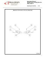
Before fitting, the ends of the table extension (1) and the table (9) must be cleaned
thoroughly. Special attention must be paid to the pin and screw holes, as the smallest
amount of dirt will prevent the correct alignment.
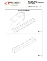
After cleaning, the table extension is pressed against the table so that the pins placed in the
table extension are inserted in the pin holes in the table. The included bolt is now inserted
into the hole and fastened with a standard spanner.
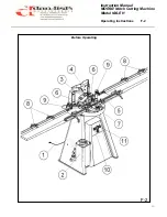
The fixed fence (2) is fitted on the table extension (location pins are fitted in the table
extension). It is secured with Allen screws. The short flip stops (5) are fitted on the fixed
fence by pushing them in from the end.
The centre stop (10) is dismounted. Underneath you will find a fitting screwed into the
grooves for the moveable fence (3). Dismount this fitting, and mount the moveable fence (3).
The centre stop (10) is fitted again. The push buttons (6) are fitted onto the moveable fence
by pushing them in from the end. The long flip stops (4) are fitted on the moveable fence (3)
by pushing them in from the end.
(Extra extension tables and supporting legs can be ordered as accessories).
Assembly Instructions E-1
Содержание MORSO NXLEH
Страница 12: ...12 Instruction Manual MORSØ Notch Cutting Machine Model NXLEH Cutting Method C 5 Functional Description C 5 ...
Страница 14: ...14 Instruction Manual MORSØ Notch Cutting Machine Model NXLEH Technical Data Technical Data D 1 ...
Страница 16: ...16 Instruction Manual MORSØ Notch Cutting Machine Model NXLEH In General E 1 Assembly Instructions E 1 ...
Страница 18: ...18 Instruction Manual MORSØ Notch Cutting Machine Model NXLEH Operating Devices F 1 Operating Instructions F 1 ...
Страница 20: ...20 Instruction Manual MORSØ Notch Cutting Machine Model NXLEH Before Operating F 2 Operating Instructions F 2 ...
Страница 34: ...34 Instruction Manual MORSØ Notch Cutting Machine Model NXLEH Working Procedure Operating Instructions F 8 F 8 ...
Страница 36: ...36 Instruction Manual MORSØ Notch Cutting Machine Model NXLEH Lubrication Instructions G 1 Service G 1 ...
Страница 38: ...38 Instruction Manual MORSØ Notch Cutting Machine Model NXLEH Changing the Hydraulic Oil Service G 2 ...
Страница 42: ...42 Instruction Manual MORSØ Notch Cutting Machine Model NXLEH Grinding of Knives G 4 Service G 4 ...


