50
LED bit: PID regulation characteristics
0:invalid
1: positive effect
When the feedback signal is greater than the given quantity of PID, the output frequency of the inverter is required to decrease (that is, reduce the feedback signal).
2: negative effect
When the feedback signal is greater than the given quantity of PID, the output frequency of the inverter is required to rise (that is, reduce the feedback signal).
LED ten bits: PID given input channel
0: keypad potentiometer
PID given quantity is given by potentiometer on the keypad.
1 Number given
PID given quantity is given by numbers and set by function code 03.01.
2 Given pressure (MPa, Kg)
Set the given pressure on 03.01 and 03.18.
LED hundred digits: PID feedback input channel
0: AI
1: Reserved
LED thousand bits: PID sleep selection
0: invalid
1: normal sleep
Specific parameters such as 03.10
~
03.13 should be set in this method.
2. Disturbed sleeping
The parameter setting is the same as when the sleep mode is selected as 0. If the PID feedback value is within the range of the set value of 03.14, the sleep
delay time will be maintained and then the disturbance sleep will be entered. When the feedback value is less than the wake-up threshold (PID polarity is positive),
wake up immediately.
03.01
Given a numerical setting
0.0
~
100.0%
0.0
When analog feedback is used, this function code realizes the setting of the closed-loop control setting with the operation panel. This function is valid only when
the closed-loop setting channel selects the digital setting (the tens place of 03.00 is 0).
Example: In the constant pressure water supply closed-loop control system, the setting of this function code should fully consider the relationship between the
range of the remote pressure gauge and its output feedback signal. For example, the range of the pressure gauge is 0
~
10MPa, corresponding to 0
~
10V voltage
output. We need a pressure of 6MPa, then the given digital quantity can be set to 6.00V, so that when the PID adjustment is stable, the required pressure is 6MPa.
03.02
Feedback channel gain
0.01
~
10.00
1.00
When the feedback channel is inconsistent with the set channel level, this function can be used to adjust the gain of the feedback channel signal.
03.03
Proportional gain P
0.01
~
5.00
2.00
03.04
Integration time Ti
0.1
~
50.0s
1.0
03.05
Derivative time Td
0.1
~
10.0s
0.0
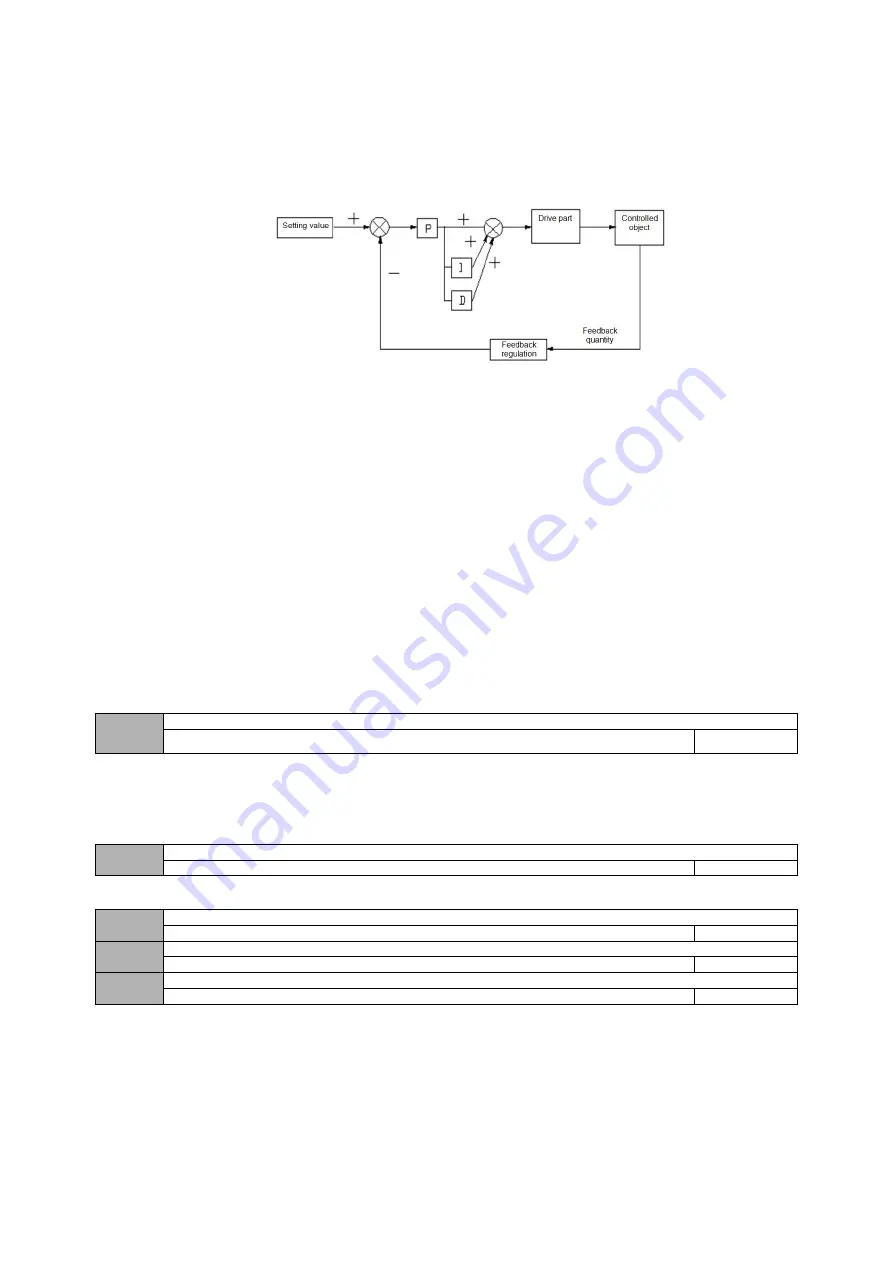
Proportional gain (Kp):
The adjustment intensity of the whole PID regulator is determined by this. And the greater the P is, the greater the adjustment intensity is. But if in too large state,
there is easy to produce oscillation.
When the feedback deviates from the set value, the deviation and output become the regulating value of proportion. If the deviation is constant, the regulating
value is also constant. Proportional adjustment can quickly show out the feedback changes, but it is impossible to achieve error-free control by proportional control
alone. The larger the proportional gain is, the faster the adjustment speed of the system will be, but if too large, oscillation will occur. The adjustment method is to set
the integration time for a longer time, and the differentiation time for zero, then use proportional control to make the system run. With changing the size of the given
quantity, it can observe the stable deviation (static difference) between the feedback signal and the set value. If the static difference changes in the direction of the set
value (for example, if the set value is increased and the feedback value is always less than the set value after the system is stable), then increasing the proportional
gain continues. Otherwise reduce the proportional gain, and repeat the above process until the static difference is relatively small (It's hard to make it without any static
errors)


