HMS Networks Intesis INKNXMHI048O000 Скачать руководство пользователя страница 13

Intesis

TM

 KNX 

– Mitsubishi Heavy Industries AC 


User’s Manual r1.2 eng


© HMS Industrial Networks S.L.U - All rights reserved 

This information is subject to change without notice


  URL    https://www.intesis.com  


                13 / 26


Connect to Mitsubishi Heavy Industries Interface


Use  the  A-B  connector  in  the  right  top  corner  of  the  front  side  of  the  Intesis

TM

  device  in 

order  to  connect  the  Mitsubishi  Heavy  Industries  network  (Superlink)  to  the  Intesis

TM

Recommended specifications of the cable for the Superlink are shown as follows: 


Size of cable : 0.75 to 1.25 square mm 


Max length of wiring : total 1000m (loop wiring is not allowed) 


Cable materials : 


Twisted Vinyl Cabtyre Cable 

VCTF  2 core  0.75 to 1.25 square mm  

Twisted Vinyl Cabtyre Cable 

VCT  2 core  0.75 to 1.25 square mm 

Twisted Vinyl Cable for Control 

CVV  2 core  0.75 to 1.25 square mm 


Table 3.1 

Cable types recommended for Superlink connection 


For prevention of electromagnetic noise malfunctions, parallel wiring with the power 
line should be avoided 

 
Select  the  appropriate  Superlink  mode  in  the  SLK  selector.  If  you  are  using  latest  Air 
Conditioner of the Mitsubishi Heavy Industries  network (New Superlink) select  NEW, if not 
select OLD.  
 
LEDs placed in the top left corner will show connection status as follows: 


LED 

Status 

Intesis

TM

 behavior 

OP 

Blinking 

Power supply OK


ERR 

Off 

No error 

HOST 

Blinking 

Internal communication OK 

PAC 

Blinking 

Communication with the Superlink network OK 


Table 3.2 

Intesis

TM

 LED status information 


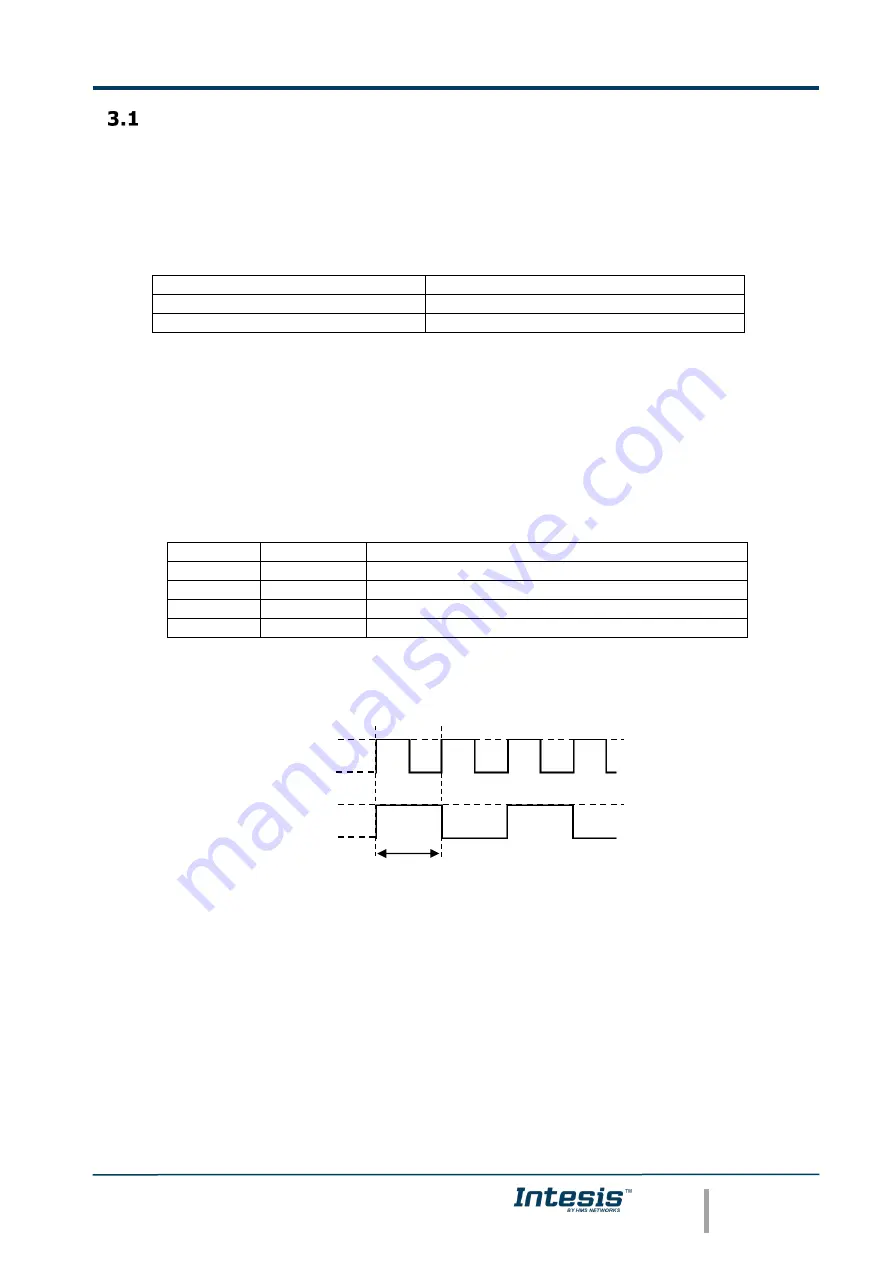
OP LED behavior must defer depending on the Superlink version, as shown in 

Figure 3.3


Figure 3.3 

OP LED blinking behavior depending on


Superlink version 


If LEDs (except ERR) are not in the states described above, check section 6.3. 


For  further  information  about  the  Superlink  network,  look  up  the  Mitsubishi  Heavy 
Industries Manual or contact your nearest Mitsubishi Heavy Industries supplier. 


Superlink-II 


Superlink-I 

On 


Off 

On 


Off 

1 sec 

Содержание Intesis INKNXMHI048O000

Страница 1: ...Gateway for integration of Mitsubishi Heavy Industries air conditioning systems into KNX TP 1 EIB control systems Application s Program Version 2 1 USER MANUAL Issue date 07 2012 r1 2 ENGLISH...

Страница 2: ...purposes and are only intended to help improve understanding of the functionality and handling of the product In view of the wide range of possible applications of the product and because of the many...

Страница 3: ...rights reserved This information is subject to change without notice URL https www intesis com 3 26 Gateway for integration of Mitsubishi Heavy Industries air conditioning systems into KNX TP 1 EIB co...

Страница 4: ...tesisTM Device Connections 12 Connect to Mitsubishi Heavy Industries Interface 13 Connect to KNX Interface 14 Connect to PC LinkBoxEIB 14 Power Device 14 LinkBoxEIB Configuration monitoring tool for I...

Страница 5: ...he KNX system read and write in the communication objects Moreover IntesisTM includes all hardware required to manage control Mitsubishi Heavy Industries indoor units without extra components needed I...

Страница 6: ...m the corresponding action in the MHI s AC system In the continuous polling if no response is detected the corresponding virtual signal inside the gateway will be activated indicating communication er...

Страница 7: ...nk or Superlink II New Superlink Indoor Unit actual address range is 00 to 47 INKNXMHI128O000 Model supporting up to 128 indoor units For Superlink II New Superlink Indoor Unit actual address range is...

Страница 8: ...ew value is updated to the bus by sending a write telegram addressed to its associated group address The rest of KNX devices in the installation that have a communication object associated to this gro...

Страница 9: ...float 32bit floating type EIS10 16bit Counter 16bit raw EIS11 32bit Counter 32bit raw EIS13 ASCII char 8bit raw EIS14 8bit Counter 8bit raw ETS3 or ETS4 software tools are not used to configure Intes...

Страница 10: ...cument Write If the option of virtual ambient temperature and SetPoint is activated to be configured from extern KNX sensor see in section 4 2 1of this document Fan Speed 14 Counter 8bit R W Fan Speed...

Страница 11: ...an 4 Dry DPT 20 105 8bit R W Operation Mode 0 Auto 1 Heat 3 Cool 9 Fan 14 Dry DPT 1 100 1bit R W Operation Mode 0 Cool 1 Heat Mode_All Cool 1 Switching 1bit R W 0 Inactive 1 Active Only one of these o...

Страница 12: ...erface connector s description 1 KNX configuration Port C1 8 Reset button Non supported 2 Non supported C2 9 Superlink selector SLK New Superlink II Old Superlink I 3 Console serial port EIA232 10 A B...

Страница 13: ...ded for Superlink connection For prevention of electromagnetic noise malfunctions parallel wiring with the power line should be avoided Select the appropriate Superlink mode in the SLK selector If you...

Страница 14: ...ser Manual Two methods to connect to the PC can be used Ethernet Using the ETH port Figure 3 1 of IntesisTM How to check connectivity is explained in section 6 3 Serial cable Connect the IntesisTM dev...

Страница 15: ...l be covered Connections configuration To configure the IntesisTM connection parameters and to see the points list press on the Config button in the menu bar see Figure 4 1 The Mitsubishi Heavy Indust...

Страница 16: ...lay after a bus reset It is expressed in seconds IntesisIP interface configuration parameters Figure 4 4 IntesisIP interface configuration 1 IP Enter the KNX physical address for the gateway 2 NetMask...

Страница 17: ...expressed in seconds s and ranges can vary from 60 s to 600 s 9 Virtual ambient temperature and setpoint Meant to be enabled when you want the temperature provided by a KNX sensor to be the reference...

Страница 18: ...ossible signal codes 3 Signal Signal s descriptive name optional Useful to identify the signal The default descriptive name corresponds to the signal s code but can be edited or modified 4 EIS KNX dat...

Страница 19: ...binary file MHI Lbox containing the configuration for the gateway will be generated and saved also into the project folder b If NO is selected remember that the binary file with the project needs to b...

Страница 20: ...ing the system In order to force a specific value to a signal double click its row in the table This will display a dialog in which the desired value can be entered see Figure 4 8 Changing its value i...

Страница 21: ...older containing these files in external media once the installation process is finished This way you will be able to do future configuration changes in case of reinstallation of LinkBoxEIB due for ex...

Страница 22: ...esired installation site For your convenience check external enclosure measures see 7 before deciding where to place the IntesisTM device 3 Connect the communication cable coming from the KNX bus to t...

Страница 23: ...ation error in the Superlink network Check the Mitsubishi Heavy Industries Superlink network and its connections Table 6 1 IntesisTM LED status information 6 3 2 Software checking Once physical connec...

Страница 24: ...to change without notice URL https www intesis com 24 26 Mechanical Electrical characteristics 1 Device can be installed in any position 5 mm 195 mm 138 mm 10 mm 15 mm Figure 7 1 External dimensions P...

Страница 25: ...R HOST PAC Push buttons 1 x Reset Device Selectors 1 x SLK selector Console port EIA232 DB9 female DCE SELV Configuration Via console port 2 Firmware Allows upgrades via console port Operational tempe...

Страница 26: ...e on power supply at primary side 33 E33 Inverter primary current error 35 E35 Cooling overload operation 36 E36 Discharge pipe temperature error 37 E37 Outdoor heat exchanger temperature thermistor a...

Отзывы: