20
Options of the linear tables
Assembly Instructions
Linear Tables HT-L
HTL-01-0-EN-1905-MA
4.8 Energy chain
Optional energy chains are available for the linear tables HT-L. The chains can be installed on either the right or the left and
is based on the selected connector position. The generously dimensioned energy chains provide enough space for the supply
cables to be carried safely. They are extremely compact and achieve space savings when integrated into the system as a
whole.
For details of the energy chain type and size, please see Table 4.6.
Table 4.6
Energy chain specifications
Manufacturer ID
1)
Inside cross-section W × H [mm]
Bending radius [mm]
2600.07.100.0
75 × 35
100
1)
Manufacturer: igus GmbH
The upper run is self-supporting but there is a surface for the lower run that supports the energy chain as it unrolls. To
prevent the cables and hoses from riding over each other, there is a partition in every second link. The connecting pieces are
of a rigid design. Strain relief combs are fitted at both ends so that the cables and hoses can be secured with cable ties. To
ensure that the energy chains are handled correctly, and that the cables and hoses are installed and secured properly, please
observe the assembly instructions from the energy chain manufacturer.
General notes:
|
For details of suitable motor and signal cables, please refer to the operating manual from the motor manufacturer.
|
Observe the minimum bending radii (industrial standard 8 × D) specified for the cables and hoses, and the associated
service life that is to be anticipated.
|
In the case of shielded cables, make sure the shields are resistant to bending.
|
Low-friction and abrasion-resistant cable/hose sheaths should be used.
|
To prevent cables and hoses with different outer sheaths from bonding, separate them with partitions.
|
Ensure twist-free installation of cables and hoses.
|
Leave enough spare room (10 to 20 %, at least 1 mm) all the way around the cables and hoses, and allow for the
lateral expansion that occurs when hoses are pressurised.
|
Make sure that the weight is distributed evenly/symmetrically. Ideally, heavy cables and hoses should be positioned at
the outer edges.
|
Provide strain relief for cables and hoses at both ends so that they are located in the neutral zone when the energy
chain is in the extended position and can move freely within its radius.
|
In the case of high acceleration values or if the cables have a wide variety of diameters, use additional partitions
where applicable.
|
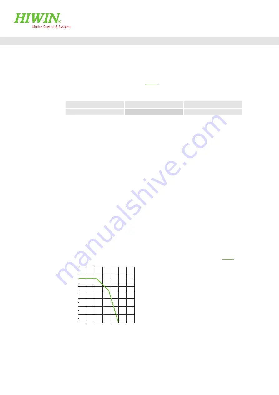
Observe the maximum additional load from cables and hoses that is permitted based on the stroke (see Fig. 4.10).
Fig. 4.10
Maximum permissible additional load as a function of the stroke,
Series 2600 (source: igus)
8.0
20.0
10.0
6.0
4.0
2.0
1.5
1.0
0.5
0
2,000
4,000
6,000
0
Fill weight [kg/m]
Stroke [mm]
Содержание 25.12345
Страница 1: ...Assembly Instructions Linear Tables HT L www hiwin de Valid from serial no HSN0000000001...
Страница 61: ...61 Assembly Instructions Linear Tables HT L HTL 01 0 EN 1905 MA Notes...
Страница 62: ...62 Assembly Instructions Linear Tables HT L HTL 01 0 EN 1905 MA Notes...
Страница 63: ...Appendix 2 Declaration of Incorporation 63 Assembly Instructions Linear Tables HT L HTL 01 0 EN 1905 MA...


