-30-
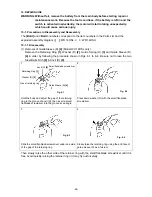
(10) Removal of the Armature Ass’y DC 14.4V
[26] <23>
Support Inner Cover (D)
[25] <22>
so that it does not
contact the fan of the Armature Ass’y DC 14.4V
[26] <23>
. With a hand press, push down the tip
portion of the Armature Ass’y DC 14.4V
[26] <23>
(pinion) to remove it.
(11) Removal of Ring Gear (E)
[20] <17>
and
Damper
[24] <21>
Remove Ring Gear (E)
[20] <17>
and O-ring (S-42)
[21] <18>
from Inner Cover (D)
[25] <22>
and remove
Damper
[24] <21>
with a small flat-blade screwdriver.
Be careful not to hurt O-ring (S-42)
[21] <18>
when
removing Ring Gear (E)
[20] <17>
and Inner Cover (D)
[25] <22>
.
10-1-2. Reassembly
Reassembly can be accomplished by following the disassembly procedures in reverse. However,
special attention should be given to the following items.
(1) Reassembly of the switch assembly
(a) Perform wiring according to the wiring diagram shown in Fig. 11 when replacing the
Controller
[46] <43>
or the DC-Speed Control Switch
[45] <42>
singly. Omit this item (a)
when replacing the Switch Ass'y
[47] <44>
.
•
Solder the internal wires (red and white) coming from the top of the Controller
[46] <43>
to the DC-Speed Control Switch
[45] <42>
. At this time, connect the internal wire (red) to
the (+) terminal of the DC-Speed Control Switch
[45] <42>
and the internal wire (white) to
the (-) terminal (Fig. 11 (a)).
Inner Cover (D)
[25] <22>
Ring Gear (E)
[20] <17>
O-ring (S-42)
[21] <18>
Ball Bearing
[23] <20>
Damper
[24] <21>
Washer (E)
[22] <19>
Fig. 10


