-37-
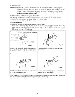
Align the protrusion of housing (A) with the concave
portion (for locking) of Magnet (D)
[28] <25>
.
Housing (A)
Pay attention to the following items in reassembly.
• Adjust the convex portion of Dust Guard Fin (C)
[30] <27>
to the concave portion of the
Brush Block
[31] <28>
(see Fig. 15).
• Adjust the concave portions (for locking) of Magnet (D)
[28] <25>
to the protrusions of
housing (A) (see Figs. 14 and 18).
• Mount the Hammer Case
[7] <3>
to the housing so that the protrusion (for locking) of the
Hammer Case
[7] <3>
contacts the support hole of the housing as shown in Fig. 20. At this
time, pass the internal wire of the LED light between the housing and the Hammer Case
[7]
<3>
as shown in Fig. 19.
• Check that the Hammer Case
[7] <3>
is mounted to the housing properly. If the Hammer
Case
[7] <3>
is not fitted in the specified groove of the housing or the rib of Inner Cover (D)
[25] <22>
is not perpendicular to the rib of the Hammer Case
[7] <3>
, remount the Hammer
Case
[7] <3>
properly (see Figs. 16, 19 and 20). Be sure to mount the Hammer Case
[7]
<3>
to the housing properly to prevent slipping off in the axial direction.
• Apply silicone grease (KS609, Shin-Etsu Chemical Co., Ltd.) to the contacting surfaces of
the FET of the DC-Speed Control Switch
[45] <42>
and Dust Guard Fin (C)
[30] <27>
then
mount them to housing (A).
NOTE:
The temperature of the FET may be high if the silicone grease is not applied. Bend the
three internal wires coming from the FET as shown in Fig. 21 so that they do not
contact Pushing Button (A) [38] <35> and also they are passed above the DC-Speed
Control Switch [45] <42>.
Fig. 18


