-32-
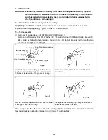
(b) When connecting the internal wires of the Brush Block
[31] <28>
to the DC-Speed Control
Switch
[45] <42>
, fasten them with the Machine Screw (W/Sp. Washer) M3 x 5
[37] <34>
paying attention to the direction of the flag terminal (Fig. 11).
(c) Fit the protrusion of the forward/reverse changeover lever of the DC-Speed Control Switch
[45] <42>
in the hole of Pushing Button (A)
[38] <35>
and mount it to housing (A). When
mounting the DC-Speed Control Switch
[45] <42>
to housing (A), check that the rotation
switch-over lever is set to "P." Otherwise, the DC-Speed Control Switch
[45] <42>
cannot
be mounted to housing (A).
• Pass the internal wire connected to the LED light between the housing ribs as shown in
Fig. 12.
Fig. 12
• Pass the internal wires connected to the DC-Speed Control Switch
[45] <42>
between
the ribs as shown in Fig. 13. First, pass the internal wire (white) between the left ribs,
then the internal wire (red) between the right inner ribs and the internal wire (brown)
between the right ribs.
• Bend the internal wire under the Controller
[46] <43>
so that it fits in the housing.
However, be careful not to break the internal wire when bending. Do not bend the internal
wire toward the noise suppressor. If the internal wire contacts the noise suppressor,
malfunction may be caused (Fig. 13).
NOTE:
If black oxide is adhered to the contact point between the terminal support and the
battery or if the plating is peeled off, the temperature of the contact point may
increase, causing malfunction of the battery or the Model WH 14DSL/WR 14DSL. In
such case, replace the DC-Speed Control Switch [45] <42> with new one (Code No.
326784) (Fig. 13).
Pass the internal wire between the housing ribs.
Internal wire (black)
Internal wire (red)


