-34-
(2) Mounting the mechanical parts
(a) Put Washer (S)
[15] <12>
onto the shaft of Spindle (D)
[17] <14>
and mount Hammer (F)
[11] <8>
containing the twenty-eight Steel Balls D3.175
[12] <9>
, Washer (J)
[13] <10>
and Hammer Spring (D)
[14] <11>
to Spindle (D)
[17] <14>
.
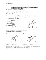
(b) Align the top of the cam groove on Spindle (D)
[17] <14>
with the steel ball guide groove
on Hammer (F)
[11] <8>
as illustrated in Fig. 8. Press down either of the raised faces of
Hammer (F)
[11] <8>
with a hand press to compress Hammer Spring (D)
[14] <11>
until
the end surface of Hammer (F)
[11] <8>
contacts Spindle (D)
[17] <14>
.
(c) Insert the two Steel Balls D5.556
[10] <7>
into the steel ball guide groove. Check that the
steel balls are properly inserted in the cam groove. Then release the hand press.
(d) Mount the hammer assembly onto the J297 base for washer (S). With a hand press, push
down the top of Spindle (D)
[17] <14>
to compress Hammer Spring (D)
[14] <11>
. On this
condition, mount Stopper
[16] <13>
onto the spindle shaft and then release the hand
press.
(e) Mounting the Armature Ass'y DC 14.4 V
[26] <23>
• Adjust the protrusions of Dust Guard Fin (C)
[30] <27>
to the concave portions of Magnet
(D)
[28] <25>
and also adjust the outside diameter of Dust Guard Fin (C)
[30] <27>
to the
outside diameter of Magnet (D)
[28] <25>
when mounting Dust Guard Fin (C)
[30] <27>
to Magnet (D)
[28] <25>
(see Fig. 14).
• Adjust the protrusions of the Side Yoke
[27] <24>
to the concave portions of Magnet (D)
[28] <25>
and also adjust the outside diameter of the Side Yoke
[27] <24>
to the outside
diameter of Magnet (D)
[28] <25>
when mounting the Side Yoke
[27] <24>
to Magnet (D)
[28] <25>
(see Fig. 14).
• Mount Yoke (A)
[29] <26>
to Magnet (D)
[28] <25>
aligning the concave portion of Yoke
(A)
[29] <26>
with the flange of Dust Guard Fin (C)
[30] <27>
. Be careful of the mounting
direction of Yoke (A)
[29] <26>
(see Fig. 14).
• Insert the two Dampers
[24] <21>
so that they fit into Inner Cover (D)
[25] <22>
. Mount
the O-ring (S-42)
[21] <18>
to Ring Gear (E)
[20] <17>
. Fit the locking rib of Ring Gear
(E)
[20] <17>
in the concave portion of the Dampers
[24] <21>
. Press-fit the Armature
Ass'y DC 14.4 V
[26] <23>
into Inner Cover (D)
[25] <22>
.
• Mount the above assembly of Magnet (D)
[28] <25>
to the Armature Ass'y DC 14.4 V
[26] <23>
.


