11.4.18
Average Power Transient Earth Fault Protection, APPTEF
GUID-079BCF22-469C-42EA-B857-E28154EC13D9 v1
Prepare the IED for verification of settings outlined in Section
"Preparing the IED to verify settings"
11.4.18.1
Verifying the signals and settings
GUID-36A0055E-CA32-4D85-A580-59032B3AC4AE v1
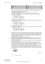
All of the following test will assume the following CT and VT ratios, and IBase and UBase settings:
•
CT ratio 1000A/1A
•
Phase-to-ground VT ratio 70kV/100V
•
Open Delta VT ratio (sqrt(3)*70kV)/100V
•
IBase=1000A
•
UBase=70kV
However, it must be noted that the secondary values given below can be used for most installations
because, usually:
1.
VT rated primary voltage value is equal to the UBase setting (70kV in the given example above)
2.
CT rated primary current value is equal to the IBase setting (1000A in the given example above)
Consequently these two quantities cancel each other in the calculations for the correct secondary
injected quantities. The frequency is not explicitly specified, use the rated frequency of the protected
network (either 50Hz or 60Hz) for signals given below.
The default setting values are used in the following test procedures if not otherwise
stated for a particular test.
Injected quantities provided below are only for the neutral current IN and the neutral voltage UN. This
assumes that these two quantities are connected to the IED on separate inputs and connected to the
APPTEF function using two SMAI preprocessing function blocks. Each of these two signals is
connected as the fourth input on respective SMAI function block.
If the above is not the case, for example; the UN is not connected to the IED but instead internally
calculated by the IED from the three phase-to-ground voltages, then simply inject the following
values for the three voltages:
UL1=sqrt(3)*UN; UL2=0V; UL3=0V
where, UN is the secondary voltage value given for every test below.
If IN is not connected to the IED but instead internally calculated by the IED from the three phase
currents, then simply inject the following values for the three currents:
IL1=IN; IL2=0A; IL3=0A
where, IN is the secondary current value given for every test below.
Test of IMinForward setting pickup value
GUID-8F3DDF4D-DAF4-4873-9AA0-682A9D8E7D68 v1
1.
Change the following settings from the default values:
•
OperationMode
= Start and Trip in order to obtain the trip signal
•
IN
>=3% (minimum value) in order not to interfere with this pickup test
1MRK 511 403-UEN Rev. L
Section 11
Testing functionality by secondary injection
Bay control REC670
117
Commissioning manual
© 2017 - 2022 Hitachi Energy. All rights reserved
Содержание REC670
Страница 1: ...Relion 670 SERIES Bay control REC670 Version 2 2 IEC Commissioning manual ...
Страница 2: ......
Страница 28: ...22 ...
Страница 54: ...48 ...
Страница 60: ...54 ...
Страница 66: ...60 ...
Страница 90: ...84 ...
Страница 212: ...206 ...
Страница 218: ...212 ...
Страница 232: ...226 ...
Страница 240: ...234 ...
Страница 241: ...235 ...

