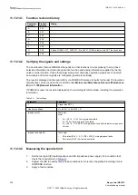
11.13.12 Function revision history
GUID-0AA99E78-0C76-48B5-AA00-8E3201C0D263 v1
Document
revision
Product
revision
History
A
2.2.1
-
B
2.2.1
-
C
2.2.2
-
D
2.2.3
-
E
2.2.3
-
F
2.2.4
-
J
2.2.4
-
K
2.2.5
New function release
11.13.13 Fault current and voltage monitoring function FLTMMXU
GUID-B976D374-CB18-441E-9A12-D4B351D6BF7F v1
GUID-22723399-65DD-44BD-B908-EDA67760065B v1
Prepare the IED for verification of settings as outlined in section
11.13.13.1 Verifying the settings
GUID-1DC53D89-47B6-4376-BA3C-A39E4F143B88 v1
Common test equipment can be used to determine the injection of current and voltage and time
measurement.
Verification of function monitoring outputs
1.
Connect the test set for injection of three-phase currents and three-phase voltage to the
appropriate current and voltage terminals of the IED.
2.
Ensure the TRIP, TRLx* output signals from PHPIOC function block connected to TRINALL,
TRINLx* input signals of SMPPTRC function block. Also, create the TRIP output signal from
SMPPTRC function block to TRIGFLTUI input signal of FLTMMXU function block.
3.
Initially inject three-phase analog magnitude and phase angle values in current and voltage
channels in such a way that PHPIOC function does not respond for such an input value.
4.
Then by ramping up the single-phase or three-phase input currents, managed to get the
TRIGFLTUI input signal as TRUE.
5.
Check that the FLTILxMAG*, FLTILxANG*, FLTINMAG, FLTINANG, FLTULxMAG*,
FLTULxANG*, FLTUNMAG, FLTUNANG, IMAXMAG, ILxMAXPK* and ILxMAX* output signals
reads the corresponding values after PostTrig setting.
6.
Check the TRIGDUR output which shows the TRIGFLTUI input signal active duration in ms.
7.
Check the TRIGTIME output which shows the IED current date and time of the instant when
TRIGFLTUI input signal become active.
* (where Lx = Phase L1, L2 and L3)
11.13.13.2 Completing the test
GUID-854DA8E8-82AC-4654-BCC8-0BFA70E0B3E3 v1
Continue to test another function or end the test by changing the Test mode setting to Off. Restore
connections and settings to their original values, if they were changed for testing purposes.
11.13.14 Fault locator LMBRFLO
M14955-2 v8
Prepare the IED for verification of settings as outlined in section
1MRK 511 403-UEN Rev. L
Section 11
Testing functionality by secondary injection
Bay control REC670
199
Commissioning manual
© 2017 - 2022 Hitachi Energy. All rights reserved
Содержание REC670
Страница 1: ...Relion 670 SERIES Bay control REC670 Version 2 2 IEC Commissioning manual ...
Страница 2: ......
Страница 28: ...22 ...
Страница 54: ...48 ...
Страница 60: ...54 ...
Страница 66: ...60 ...
Страница 90: ...84 ...
Страница 212: ...206 ...
Страница 218: ...212 ...
Страница 232: ...226 ...
Страница 240: ...234 ...
Страница 241: ...235 ...


