All references to CT and VT must be interpreted as analog values received from
merging units (MU) via IEC/UCA 61850-9-2LE communication protocol, analog
values received from the transformer input module, or analog values received from
the LDCM.
When using a MU test simulator, make sure it is set to the correct SVID and that the
system frequency is set to the same as in the IED.
Please observe the measuring accuracy of the IED, the test equipment and the
angular accuracy for both of them.
Consider the configured logic from the function block to the output contacts when
measuring the operate time.
After intense testing, it is important that the IED is not immediately restarted, which
might cause a faulty trip due to flash memory restrictions. Some time must pass
before the IED is restarted. For more information about the flash memory, refer to
section “Configuring the IED and changing settings”.
If the IED is used together with a merging unit and no time synchronization is
available, for example, in the laboratory test, the IED will synchronize to the SV data
stream. During the re-synchronization, the protection functions will be blocked once
a second for about 45 ms, and this will continue for up to 10 minutes. To avoid this,
configure PTP (IEEE 1588) to
On
for the access point where the merging unit is
configured.
10.1.2
Preparing the IED to verify settings
M11741-2 v12
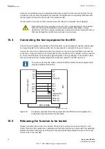
If a test switch is included, start preparation by making the necessary connections to the test switch.
This means connecting the test equipment according to a specific and designated IED terminal
diagram.
Put the IED into the test mode to facilitate the test of individual functions and prevent unwanted
operation caused by other functions. The busbar differential protection is not included in the test
mode and is not prevented to operate during the test operations. The test switch should then be
connected to the IED.
Verify that analog input signals from the analog input module are measured and recorded correctly
by injecting currents and voltages required by the specific IED.
To make testing even more effective, use PCM600. PCM600 includes the Signal monitoring tool,
which is useful in reading the individual currents and voltages, their amplitudes and phase angles. In
addition, PCM600 contains the Disturbance handling tool. The content of reports generated by the
Disturbance handling tool can be configured which makes the work more efficient. For example, the
tool may be configured to only show time tagged events and to exclude analog information and so
on.
Check the disturbance report settings to ensure that the indications are correct.
For information about the functions to test, for example signal or parameter names, see the technical
manual. The correct initiation of the disturbance recorder is made on start and/or release or trip from
Section 10
1MRK 511 403-UEN Rev. L
Testing IED operation
74
Bay control REC670
Commissioning manual
© 2017 - 2022 Hitachi Energy. All rights reserved
Содержание REC670
Страница 1: ...Relion 670 SERIES Bay control REC670 Version 2 2 IEC Commissioning manual ...
Страница 2: ......
Страница 28: ...22 ...
Страница 54: ...48 ...
Страница 60: ...54 ...
Страница 66: ...60 ...
Страница 90: ...84 ...
Страница 212: ...206 ...
Страница 218: ...212 ...
Страница 232: ...226 ...
Страница 240: ...234 ...
Страница 241: ...235 ...


