Chapter 8 Register Structure
8.4 Data
Registers
EH-ETH2 has data registers (WXs0, WYs1)
(*1)
. Data registers consist of Partial data of Status/Control
Registers and flags to reset the Ethernet port.
Data registers can be read or write by Arithmetic command. To WXs0 data register, the information of
Module status register (MDSR) is assigned. To WYs1 data register, the bits of ERR Clear (EC0) and IER
Clear (EC1) in Module control register (MDCR) and the one to reset the Ethernet port are assigned.
Therefore, the information of Module status register (MDSR) can be confirmed on WXs0 and the bits of ERR
Clear (EC0) and IER Clear (EC1) in Module control register (MDCR) can be set from WYs1.
*1 : “s” means slot No. that EH-ETH2 is allocated.
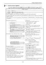
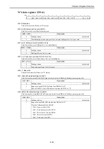
WX data register (WXs0)
Bit
15
14
13
12
11
10 9 8 7 6 5 4 3 2 1 0
+0
- - - - - - - - -
OPM
-
EIE
AVR
ATR
IERR
ERR
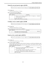
Bit 15-7: Reserved
These bits are reserved bits. Usually "0" are set.
Bit 6: Operation mode bit (OPM)
The status of DIP-switch 1 is reflected on this bit.
Bit6: OPM
Description
0
Normal operation mode
1
The other mode.
Bit 5: Reserved
These bits are reserved bits. Usually "0" are set.
Bit 4: Ethernet information configuration error bit (EIE)
Illegal Ethernet information is set. In the case of this bit set "1", IER LED turns on.
Bit4: EIE
Description
0
There is no error.
1
The illegal Ethernet information configuration (set-up) is detected.
Bit 3: Existence response bit (AVR)
The result of general working check for EH-ETH2. The data (IAV bit of Control Register) will be reflected here.
Bit3: AVR
Description
0
1
The data set in Existence confirmation Request bit (IAV) of Control area are reflected.
Bit 2: Automatic Sending/Receiving enable bit (ATR)
This bit shows the current specified status of Automatic Sending/Receiving function is disable or enable.
Bit2: ATR
Description
0
Automatic Sending/Receiving function is disable.
1
Automatic Sending/Receiving function is enable.
Bit 1: IER LED lighting condition bit (IERR)
This bit shows the current condition of IER LED.
Bit1: IERR
Description
0
IER LED is turned off.
1
IER LED is turned on.
Bit 0: ERR LED lighting condition bit (ERR)
This bit show the current condition of ERR LED.
Bit0: ERR
Description
0
ERR LED is turned off.
1
ERR LED is turned on.
8-23

