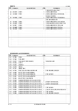
Hitachi CV 350V Скачать руководство пользователя страница 12

PARTS

CV 350V

   DESCRIPTION

    REMARKS

1

301653

TAPPING SCREW (W/FLANGE) D4 X 20 (BLACK)

7

2

337668

NEEDLE ROLLER

1

3

337662

HEAD CASE

1

4

337665

SLEEVE CAP

1

5

337671

TOOL SHAFT

1

6

337667

PUSHING PIECE

1

7

337666

LEVER

1

8

337670

SEAL LOCK SCREW M4 X 6

1

9

337669

LEVER GUIDE

1

*

10

360984C

ARMATURE ASS'Y SET 110V

1

INCLUD.11-21

*

10

360984E

ARMATURE ASS'Y SET 220V-230V

1

INCLUD.11-21

*

10

360984F

ARMATURE ASS'Y SET 240V

1

INCLUD.11-21

11

337663

BEARING HOLDER

1

12

337664

O-RING (S-35)

1

13

994251

RETAINING RING FOR D7 SHAFT

1

14

338037

BALL BEARING-R 607VV

1

15

337675

BALANCER

1

16

6000VV

BALL BEARING 6000VVCMPS2L

1

17

337672

BEARING COVER

1

18

321722

DUST SEAL

1

19

626VVM

BALL BEARING 626VVC2PS2L

1

20

337676

SENSOR MAGNET

1

21

337677

PUSHING NUT

1

22

337683

FAN GUIDE

1

*

23

340890C

STATOR 110V

1

*

23

340890E

STATOR 220V-230V

1

*

23

340890F

STATOR 240V

1

24

337661

HEAD COVER (A).(B) SET

1

25

313687

TAPPING SCREW (W/FLANGE) D3 X 16 (BLACK)

4

26

337680

SLIDE KNOB

1

27

337660

HOUSING

1

28

NAME PLATE

1

29

337679

SLIDE BAR

1

30

333844

BRUSH HOLDER

1

31

328210

TAPPING SCREW D3 X 8

4

32

999005

CARBON BRUSH (1 PAIR)

2

33

337678

TAIL COVER (A).(B) SET

1

34

335460

MICRO SWITCH

1

*

35

337681

CONTROLLER 100V-110V

1

*

35

337682

CONTROLLER 220V-240V

1

*

36

334379

FERRITE CORE

1

FOR EUROPE,AUS,NZL,SAF,RUS,TUR,GBR (230V)

*

37

953327

CORD ARMOR D8.8

1

*

37

938051

CORD ARMOR D10.1

1

38

937631

CORD CLIP

1

39

984750

TAPPING SCREW (W/FLANGE) D4 X 16

2

*

40

334472

NOISE SUPPRESSOR

1

FOR EUROPE,AUS,NZL,SAF,RUS,

TUR,GBR,TPE,UAE (110V)

41

338119

INTERNAL WIRE

1

42

959140

CONNECTOR 50091 (10 PCS.)

3

*

43

314854

EARTH TERMINAL

1

FOR EUROPE,AUS,NZL,SAF,RUS,

- 2 -

12 - 14

          *ALTERNATIVE PARTS

ITEM

NO.

NO.

USED

CODE NO.

Содержание CV 350V

Страница 1: ...T NAME Hitachi Multi Tool Model CV 350V CONTENTS Page LIST No CV 350V E728 Dec 2014 REPAIR GUIDE 1 1 Precautions on disassembly and reassembly 1 STANDARD REPAIR TIME UNIT SCHEDULES 9 C Overseas Sales Division ...

Страница 2: ...s D3 x 16 25 and remove Head Cover A B Set 24 2 Loosen the four Screws D4 x 20 1 and remove the Head Case 3 from the Housing 27 3 Pull out the Armature Ass y Set 10 3 Removing the lever 1 Place the Head Case 3 on an adequate stand with the Lever 7 fitted to the Lever Guide 9 Using a hand press push the Needle Roller 2 to remove it Remove the Lever 7 and the Pushing Piece 6 2 Loosen the Screw M4 x ...

Страница 3: ...0VV 16 touches the fan of the Armature Ass y Set 10 Do not push in the Ball Bearing 6000VV 16 excessively Do not forget to mount the Bearing Cover 17 3 Mounting the stator Mount the Slide Knob 26 and Slide Bar 29 to the Housing 27 first Then mount the Stator 23 in the Housing 27 being careful of the orientation of the internal wires Reassembly Thick Pushing Piece 6 Lever Guide 9 Head Case 3 Needle...

Страница 4: ...dered portions with heat shrinkable tubes Put the red internal wire in the groove Put the black internal wire in the groove Put the blue internal wire in the groove Controller 35 Noise Suppressor 40 Ferrite Core 36 Crimp the Earth Terminal 43 Wind the internal wire twice 40 Bend at the terminal joints Put two brown internal wires of the Stator 23 in the groove Put two blue internal wires of the St...

Страница 5: ...ove Put the black tube and blue internal wire of the Stator 23 and white internal wire of the Noise Suppressor 40 in the groove Insert the Earth Terminal 43 into the Housing 27 Earth Terminal 43 Bend Cord Clip 38 Micro Switch 34 Controller 35 Noise Suppressor 40 After soldering wrap the soldered portions with heat shrinkable tubes Controller 35 Put red internal wire in the groove Put the black int...

Страница 6: ...e Put the blue internal wire of the Stator 23 in the groove Slide Bar 29 Slide Knob 26 Tab Tail cover A Controller 35 Put the Cord 44 through the Cord Armor 37 Micro Switch 34 Internal Wire 41 Put the red internal wire in the groove Put the black internal wire in the groove Put the blue internal wire in the groove Controller 35 Bend After soldering wrap the soldered portions with heat shrinkable t...

Страница 7: ...4 to mount c Pull the guide sleeve by holding the Sleeve Cap 4 and turn it to the opposite side Check that the mark on the Sleeve Cap 4 is aligned with the mark on Head Cover A B Set 24 d Turn the guide sleeve toward the mark and insert the Tool Shaft 5 e Turn the guide sleeve toward the mark and pull the lever down being careful not to pinch your fingers 1 Pull up the lever until it becomes paral...

Страница 8: ...ory can be mounted and removed securely 3 Check that the Tool Shaft 5 can be pushed in and pulled out normally when the mark on Head Cover A B Set 24 is aligned with the mark on the Sleeve Cap 4 and that the Tool Shaft 5 cannot be pulled out when the mark is aligned with the mark 4 Cut wood at the dial setting A Check that the tool runs fast during cutting and slow after cutting On completion of d...

Страница 9: ...r 23 Blue Blue Brown Brown White White Internal Wire 41 Controller 35 Stator 23 Internal Wire 41 Micro Switch 34 White White Brown Black Blue Red Black A B C White Black Black White Cord 44 Noise Suppressor 40 Black Black Red White Connector 42 Connector 42 Connector 42 Connector 42 Connector 42 Connector 42 Cord 44 Brown Blue Micro Switch 34 Red Black Blue Controller 35 A C B Stator 23 Blue Blue ...

Страница 10: ...lide Knob Fan Guide Armature Ass y Set Bearing Holder Ball Bearing R 607VV Balancer Ball Bearing 6000VV Work Flow Carbon Brush Micro Switch Tail Cover A B Set Cord Cord Armor Controller Head Case Ass y Head Cover A B Set Lever Needle Roller Lever Guide Tool Shaft STANDARD REPAIR TIME UNIT SCHEDULES ...

Страница 11: ...0V MULTI TOOL LIST NO E728 2014 12 10 E1 36 508 1 2 3 4 5 6 7 8 9 11 12 13 14 15 10 16 17 18 19 20 21 22 23 24 25 26 27 28 29 30 1 31 32 34 35 33 40 41 42 37 38 39 44 501 503 504 505 506 502 507 510 509 511 512 43 ...

Страница 12: ...337677 PUSHING NUT 1 22 337683 FAN GUIDE 1 23 340890C STATOR 110V 1 23 340890E STATOR 220V 230V 1 23 340890F STATOR 240V 1 24 337661 HEAD COVER A B SET 1 25 313687 TAPPING SCREW W FLANGE D3 X 16 BLACK 4 26 337680 SLIDE KNOB 1 27 337660 HOUSING 1 28 NAME PLATE 1 29 337679 SLIDE BAR 1 30 333844 BRUSH HOLDER 1 31 328210 TAPPING SCREW D3 X 8 4 32 999005 CARBON BRUSH 1 PAIR 2 33 337678 TAIL COVER A B S...

Страница 13: ... 507 337937 INNER TRAY 1 508 337922 DUST COLLECTION ADAPTER SET 1 FOR NOR SWE DEN FIN 509 335868 MULTI TOOL BLADE MW85S 1 509 335880 MULTI TOOL BLADE MD85SB 1 FOR AUS NZL 510 335881 MULTI TOOL BLADE MD28PB 1 511 335903 MULTI TOOL PAD MU93D 1 512 338252 SANDING PAPERS 94 X 94 AA60 10 PCS 1 512 338253 SANDING PAPERS 94 X 94 AA80 10 PCS 1 EXCEPT FOR AUS NZL 512 338254 SANDING PAPERS 94 X 94 AA100 10 ...

Страница 14: ...893 MULTI TOOL BLADE MU65CF 1 625 335892 MULTI TOOL BLADE MU85CF 1 626 335901 MULTI TOOL BLADE MU52PKR 1 627 335902 MULTI TOOL BLADE MU52PK 1 628 335900 MULTI TOOL BLADE MU28PK 1 629 335897 MULTI TOOL BLADE MA85SH 1 630 335899 MULTI TOOL BLADE MA85SHT 1 631 335877 MULTI TOOL BLADE MU28PKS 1 632 335904 MULTI TOOL BLADE MA70DHX 1 633 335905 MULTI TOOL BLADE MA78DH 1 634 335890 MULTI TOOL BLADE MA65S...

Отзывы: