


Table 1-7 Location of installable components
Symbol
Component
0
HDD #0
1
HDD #1
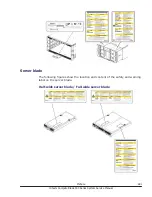
Disk drive numbering: CB 540A A1/B1
The disk drive numbering in a server blade is #0 to #1/2 from the left to
right, as viewed from the front of the server blade. The same numbering
applies to all server blades in the server chassis.
Figure 1-12 Disk drive location
Table 1-8 Location of installable components
Symbol
Component
0
HDD #0
1
HDD #1 (Using the RAID Mezzanine or Combo Mezzanine) /
HDD #2 (Using the Onboard RAID)
Disk drive numbering: CB 520X B1/B2/B3
The disk drive numbering in a server blade is #0 to #2 from the left to right,
as viewed from the front of the server blade. The same numbering applies to
all server blades in the server chassis.
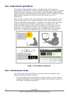
Introduction
1-9
Hitachi Compute Blade 500 Series System Service Manual
Содержание CB 520A A1
Страница 26: ...xxvi Preface Hitachi Compute Blade 500 Series System Service Manual ...
Страница 152: ...4 64 Common process for replacement Hitachi Compute Blade 500 Series System Service Manual ...
Страница 294: ...6 12 Identifying RAID rebuild status Hitachi Compute Blade 500 Series System Service Manual ...
Страница 432: ...9 16 Updating firmware Hitachi Compute Blade 500 Series System Service Manual ...
Страница 439: ...Change LOM configuration 10 7 Hitachi Compute Blade 500 Series System Service Manual ...
Страница 442: ...10 10 Change LOM configuration Hitachi Compute Blade 500 Series System Service Manual ...
Страница 450: ...10 18 Change LOM configuration Hitachi Compute Blade 500 Series System Service Manual ...
Страница 464: ...11 14 Troubleshooting Hitachi Compute Blade 500 Series System Service Manual ...
Страница 465: ...Hitachi Compute Blade 500 Series System Service Manual ...