Assembly 51
2
1
3
4
5
6
5
6
8
10
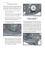
PHOTO NO. DCP0542
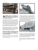
2. Remove the plugs from both hydraulic cylin-
ders and replace with 3/4” ORB to 9/16” JIC
straight adapters (Item 5).
3. Attach the 1/4 x 126” hoses (Item 6) to the
adapters coming out of the hydraulic cyl-
inders. The 90 degree elbow on the hoses
should be on the cylinder end of the hose.
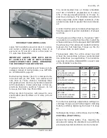
4. Run both hoses (base end hose (Item 8) and
rod end hose (Item 10) from each hydraulic
cylinder to the center of the machine. Refer
to Photo DCP0542. The hoses should be run
behind the formed angle and the upright flat
bar gussets (Item 7) on the rear of the shred-
der. Run the hoses to the center of the shred-
der from both sides. Refer to Photo DCP
0549.
7
7
PHOTO NO. DCP0549
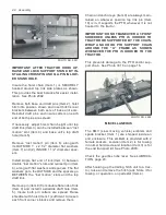
5. The hoses connected to the rod end ports
(Item 10) should be connected to one tee
(Item 9) and the hoses from the base end
ports (Item 8) should be connected to the oth-
er tee (Item 9). Refer to Photo DCP0554.
9
8
10
11
11
9
10
8
13
PHOTO NO. DCP0554
6. Connect the two 3/8” x 120” hoses (Item 11)
to the fitting tees (Item 9). Run the hoses
forward and through the hose carrier (Item
13) provided with the hitch. Refer to Photo
DCP0554.
12
11
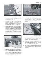
PHOTO NO. DCP0557
7. The hose carrier will lift the hoses over the
gearbox and drive lines. Turn the ISO male
connectors (Item 12) onto the ORB end of
the hoses. Refer to Photo DCP0557.
8. Connect the hoses to a tractor and cycle
the cylinders back and forth until all air is
worked out of the hydraulic system.
9. Remove the blocks supporting the hydraulic
cylinders and connect the rod ends to rock
shaft links.


