Commercial anaerobic threadlocks have
installation instructions, and SAFETY CAU-
TIONS, on their containers. These should
be adhered to.
8. Reinstall and realign previously removed
sheave and belt.
INNER ROTOR BEARINGS
1. To remove the rotor the shredder must be
turned upside down.
2. Raise front and securely block front corners.
Remove SMV, PTO, and 3 point, or trailing,
hitch.
3. Remove belt and driveN sheave. If unit is
equipped with aftermarket hydraulics, remove
hose support and fully retract cylinder(s).
Loosen both inner and outer bearing’s lube
tube zerk nuts and detach lube tubes from
their supports.
4. Temporarily insure end panel shields are
latched shut. Reinstall hitch draft pins (Item 2
Photo 2990A) on page 32 and their cotters.
WARNING: DEATH OR SERIOUS IN-
JURY CAN RESULT. DO NOT ATTEMPT
TO REMOVE A ROTOR FROM UNDER
NEATH A SHREDDER IN ITS OPERATING PO-
SITION.
NEVER ATTEMPT TO REMOVE A ROTOR WITH
THE UNIT UPENDED IN A VERTICAL POSI-
TION.
WARNING: DEATH OR SERIOUS IN-
JURY CAN RESULT. USE HOISTING
EQUIPMENT CAPABLE OF SAFELY
HANDLING NO LESS THAN 3 TON (6000#).
WARNING: DEATH OR SERIOUS IN-
JURY CAN RESULT. CLEAR PEOPLE
FROM WORK AREA WHEN TIPPING
SHREDDER OVER. DO NOT WORK ON SOFT,
OR UNEVEN, GROUND. LIFT ONLY FROM
MAIN FRAME 1 INCH DIAMETER HITCH PINS.
Service 31
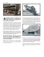
4. Remove (2) 3/8” Allen set screws from the
inner race of the outer rotor bearing (Item
1) which are factory retained with anaerobic
thread lock Perma-Lok HM118 (red) or Lock-
tite 242 (blue).
2
5
3
4
4
4
4
2
6
7
1
PHOTO NO. DCP0659
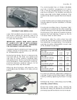
5. Remove (4) 1/2” locknuts (Item 6) which are
factory retained with anaerobic threadlock
(eg. Lock-tite 242 (blue) or Perma-Lok HM
118 (red). Modestly pry plate (Item 7) out-
ward to start bearing (Item 1) off shaft.
6. A varying quantity of 2 3/16” nominal. I.D.
washers are factory installed between the
inner end of bearing (Item 1) and the shoul-
der on shaft (Item 5). Because replacement
bearings vary in axial dimensions, care
must be exercised to FULLY WASHER THE
SPACE BETWEEN THE BEARING AND
SHAFT SHOULDER. Reinstall plate (Item
7) and bearing (Item 1) by temporarily snug-
ging up 2 each of their bolts (without anti-
wrap shields). Visually check above cited
washers to insure no looseness, or substan-
tial axial preload, exists. 2 3/16 inch nominal
I.D. washers are available as part numbers:
Washer
Part Number
1/16” Thick
79202329
1/8” Thick
79202328
7. After the washers have been checked, torque
bearing mounting bolts and Allen set screws.
Torque the Allen screws once, loosen and
torque a second time. Reinstall anti-wrap
shields (Item 8) and torque support plate
bolts. See Photo DCP0575 on page 29.


