


Assembly 49
PHOTO NO. 2993
PREDELIVERY RUN IN
Refer to DELIVERY check list, and routinely
perform all relevant checks thereon.
Refer to FIELD PREPARATION page 11 and in-
sure specific hitch, PTO, wheel settings, etc. are
configured to customer’s stated requirements.
CAUTION: DEATH OR SERIOUS IN-
JURY CAN RESULT. DISENGAGE
PTO, STOP TRACTOR ENGINE, SET
BRAKES, REMOVE KEY AND ALLOW EQUIP-
MENT TO COME TO A COMPLETE STOP BE-
FORE:
CLEANING, UNCLOGGING, LUBRICATING,
INSPECTING, OR OTHERWISE SERVICING
ANY PART OF THIS EQUIPMENT.
DO NOT INSPECT AND/OR SERVICE A
SHREDDER IN A RAISED POSITION UNLESS
IT HAS BEEN SECURELY BLOCKED FROM
UNEXPECTED FALLING.
KEEP OFF, KEEP OTHERS OFF AND MAKE
CERTAIN EVERYONE IS CLEAR BEFORE
STARTING, ACTUATING HYDRAULICS, AND
DURING OPERATION.
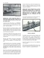
END TRANSPORT ACCESSORY
The hydraulic end transport 9.5L x 15” 8 ply (im-
plement) tires are to be inflated to 40 psi.
OPERATION
1. With the tractor connected to the field hitch,
insert the male couplers into the tractor hy-
draulic system. Cycle the machine up and
down several times to make sure all air is
purged from the hydraulic hoses and cylin-
ders. Check the hydraulic level on the trac-
tor and refill as needed.
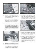
2. Using the tractor controls, fully extend the
end transport cylinders. Move the jack to
the tube on the end transport hitch. Raise or
lower the jack so the hitch will be in position
to hook to the drawbar of the tractor.
3. With the end transport cylinders fully ex-
tended, insert the (2) cylinder stops over
the cylinder rods to hold the cylinders in the
fully extended position. Secure the cylinder
stops in position using the (4) tab lock pins.
Slowly collapse the hydraulic end transport
cylinders so that the cylinder stops are held
tight by the cylinder. Fully raise the rockshaft
tires.
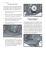
4. Remove the PTO shaft holder pin. Lift the
PTO shaft onto the PTO shaft holder. Re-
install the pin to secure the PTO shaft in
position. Secure the pin using the removed
hair pin cotter. Unhook the tractor from the
shredder field hitch. Insert the hydraulic
coupler into the slotted holes of the hydrau-
lic coupler holder plate. Attach the tractor to
the end transport hitch.
5. Verify that the sliding tongue hitch is se-
curely pinned, safety chain is installed and
SMV is mounted on end shield bracket pro-
vided. The SMV’s reflective surface must
be visible from the rear. DO NOT EXCEED
SPEEDS OF 25 MPH (40Km/h).
PHOTO NO. DSCN4638