Assembly 47
ALL 3 POINT PTO’S ARE NON C.V. and identi-
fied by front yokes joined with a conventional
front cross.
IMPORTANT: IT IS CRITICAL TO KNOW WHAT
TRACTOR CONFIGURATION IS INVOLVED
BEFORE HOOKUP. THE PROPER SHREDDER
PTO MUST BE USED, OTHERWISE POTEN-
TIAL EQUIPMENT DAMAGE CAN RESULT.
IDENTIFY CORRECT SHREDDER PTO FOR
TRACTOR USED BY CHECKING FORWARD
YOKE SPLINE AND NOTING WHETHER IT
IS A C.V. OR NON C.V. DO NOT INTERMIX
FRONT AND REAR HALVES BETWEEN DIF-
FERENT NON CV PTO’s.
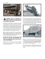
All shredder PTO’s have similar sliding yoke cou-
plers at tractor and gearbox ends. GEARBOX
ENDS ARE IDENTIFIED BY AN OVERRUN-
NING CLUTCH (Item 1). See Photo 2969A.
Clean gearbox spline of any encrusted dirt or
grease and lightly oil it. Slide outer PTO collar
(Item 2) toward its adjacent yoke (Item 3) and
slide PTO over the gearbox spline. Reverse the
sliding collar to lock the assemblies together.
IMPORTANT: NEVER TOW A TRAILED
SHREDDER IN FIELD MODE UNLESS THE
PTO IS PROPERLY HOOKED UP TO BOTH
TRACTOR AND SHREDDER. OTHERWISE,
IT CAN BE DAMAGED. IF TOWED WITHOUT
FULL HOOKUP, DETACH ENTIRE PTO FROM
GEARBOX AND SECURE IT BEHIND CROSS
DRIVE SHAFT SHIELD.
PHOTO NO. 2969A
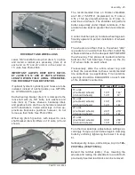
3 POINT HITCH
NOTICE: MOVE HITCH JACK (ITEM 1) FROM
SHIPPING POSITION TO PEDESTAL (ITEM 2)
AT TOP OF GEARCASE. THIS JACK IS NOT
NEEDED ON 3 POINT UNITS, EXCEPT WHEN
AN END TRANSPORT ACCESSORY IS USED.
This hitch weighs 300# (136 kg.); Therefore,
use a hoist to move it into working position. See
Photo 3139.
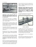
The bundle contains the hitch “A” frame (Item
3), separate draft link (Item 4) and separate sup-
port stand (Item 5). The tractor’s 2 lower and 1
upper hitch pins (Item 6), along with their 7/16”
diameter lynch pins, and a PTO support chain,
are factory installed. Also factory installed are
tractor hitch pin spacers for Cat. II, III and IIIN
applications. All 3 tractor hitch pins should be
left as factory installed until customer’s final
field preparation. Clip dunnage and remove
support stand and draft link.
PHOTO NO. 3139
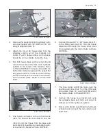
Install support stand assembly (Item 1) with pin
(Item 2), along with its cotters. Install cross pin
(Item 3) and Q.A. pin (Item 4) in hookup and
storage hole (Item 5). Hole (Item 6) is for shred-
der operation and transport. See Photo 3031.


