CONFIGURATION
17
5 Communication LEDs - Troubleshooting
The AT Communications Module pc board (
A12
) features LEDs to indicate the status of
communications with the Main Control board (A1), the serial ports, and the
optional
Ethernet port. Reference
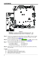
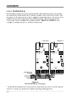
Figure 2
on Page 5 for the location of the following LEDs.
5.1 Main Control Board STATUS LED
The STATUS LED (
D1
) is a red indicator located to the left of dipswitch (
S1
). This LED
will blink when the main control board and communications module exchange data. This
LED should blink several times a second.
If the STATUS LED is always
on
or
off
, this indicates that the main control board and
communications module are not communicating. This may indicate a problem with either
the main control board or the communications module.
5.2 TXD & RXD Serial Port LEDs
The yellow TXD LED (
D3
) and green RXD LED (
D2
) are located along the left edge of the
communications module about 2 inches from the bottom of the board. The RXD LED will
flash green every time the communication module detects activity on the serial network. The
TXD LED will flash yellow every time the communication module sends data to the serial
network. Under normal operation the TXD LED will be flashing at the charger poll rate, and
the RXD LED will be flashing at the poll rate or faster.
Note that the RXD LED flashes any time activity is detected on the network. This activity
may be messages to/from other devices on the network. In addition, the flashing RXD LED
only indicates that there are transitions on the network. It does not indicate valid framed
command messages are being received that are addressed to the communication module.
A flashing yellow TXD LED indicates that a valid correctly formatted message was received
by the communication module and the communication module responded to the received
message. The yellow TXD LED flashing at the charger poll rate typically indicates that the
network connection is working, however since it located on the charger side of the isolation
barrier, their still could be a problem on the network side of the isolation barrier.
If either or both the RXD and TXD LEDs are always
on
or
off
, this may indicate a
networking wiring error, a network problem, or incorrect configuration.
5.3 ACT, LINK, and SPEED Ethernet Port LEDs
These three (3) Ethernet status LEDs are located below Ethernet connection port (
J1
). These
LEDs will only be relevant if the AT Communications module features the Ethernet option.
The green LINK LED (
D6
) when lit indicates that a good link has been established. The
yellow ACT LED (
D4
) flashes when there is activity on the network. The orange SPEED
LED (
D5
) indicates the network BAUD rate. If the communication module is connected to a
10Mb/s network, the SPEED LED will be
off
. The SPEED LED will be lit if the
communications module is connected to a 100Mb/s network.

