


HARDWARE
12
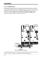
3.3 Ethernet
Connection
(optional)
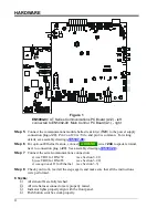
A special AT Series Communications Module (p/n
EJ5037-2
#
) can also be supplied, which
supports both 10/100 MB copper Ethernet connections. These options have an RJ45 Ethernet
socket (
J1
) installed onto a special A12 Communications PC Board (p/n
EN5004-01
). See
Figure 2
on page 5 for details.
To enable the Ethernet interface, set configuration switch (
S1-8
) to the
ON
position. The
Ethernet interface will automatically detect and select the correct BAUD rate. To connect
the Communications Module to your network, simply connect standard Cat 5/6 cable with
RJ45 plug, from your network into Ethernet Socket (
A12-J1
). Turn on dipswitch (
S1-8
).
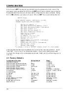
Refer to Factory Defaults Section 4.3 on page 16 for instructions on how to use the Set Up
terminal emulator. This section describes how to configure the IP address, netmask, and
gateway settings and how to enable Modbus and DNP protocols to use the Ethernet interface.
- -
NOTICE
- -
Older AT Series Communications Modules were sometimes
supplied with a
separate
Ethernet Gateway (p/n
EJ5226-
##
), which is no
longer produced. See User Instruction (
) for legacy details.
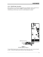
3.4 Serial Fiber Optics Modem
An optional fiber optic to serial converter is available for the AT Series Communications
Module. When ordered, this option (p/n
EJ5230-
##
) will be installed at the factory. It will
allow direct connection of fiber connections compatible with standard "B&B" and "Dymec"
type converters. Please refer to the following supplemental documentation for the available
Fiber Optics Interface options.
EJ5230-04
http://www.ATSeries.net/PDFs/EJ5230-04.pdf
"B&B"
Fiber Optics
Interface for
130Vdc
AT Comm
EJ5230-1X
http://www.ATSeries.net/PDFs/EJ5230-1X.pdf
"DYMEC RS-485 "
Fiber Optics
Interface for AT Comm
EJ5230-2X
http://www.ATSeries.net/PDFs/EJ5230-2X.pdf
"DYMEC RS-232 "
Fiber Optics
Interface for AT Comm
3.5 Ethernet over Fiber
An optional Ethernet fiber optic module is available for the AT Series Communications
Module. When ordered, this option (p/n
EJ5284-
##
) will be installed at the factory. It will
allow direct connection of various standard Ethernet fiber topologies. The Ethernet fiber
optics module incorporates a standard Small Form Pluggable (SFP) module socket, such that
various BAUD rates, fiber types, and connectors can be supported. Contact the factory for
the specific needs of your interface requirements.
3.6 Using a Legacy Telephone Modem
An "industry-standard" V.92 56K modem is compatible with the AT Series Communications
Module to connect it to an analog phone line. Refer to the special User Instructions
(
) for analog modem connection details.
The monitoring computer system will also need a modem. The computer system will dial out
to the AT Series charger. The modem connected at the charger will answer the call and start
communicating. The following instructions are for a
U.S. Robotics
modem product #
USR5686D
(or equivalent) with the auto-answer feature enabled.