background image

Smart Camera User Manual 

12 


The camera adopts the C-Mount lens interface. 

1.4.3


Interfaces Introduction 

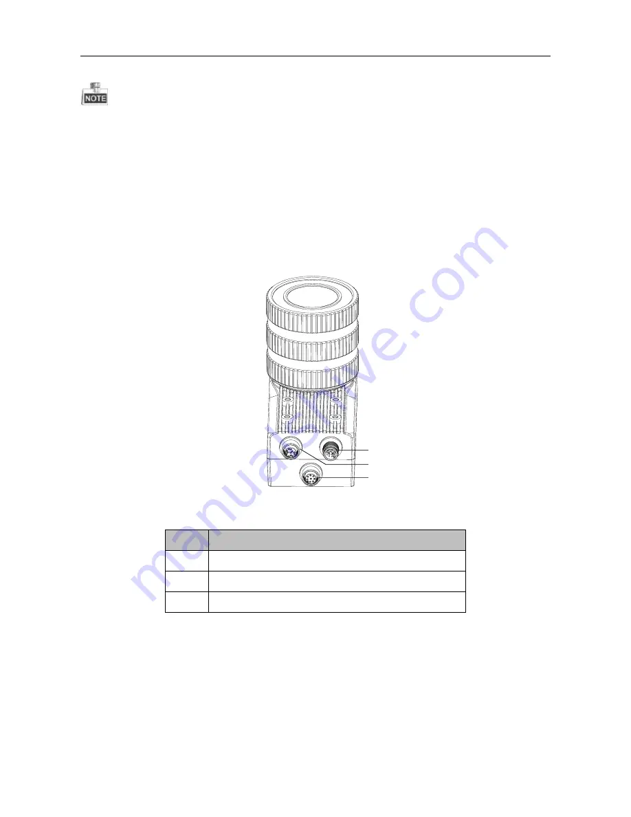
The figure below shows the interfaces of the  smart camera with  light  source and camera housing, 

including  aviation  plug  to  RJ45  network  interface,  12-pin  power  and  I/O  interface,  and  5-pin 

external  light  source  interface.  The  camera  interfaces  with  screw  thread  for  connection  between 

camera and cable avoid loosening due to vibration. 

2

3

1


Figure 1. 5


Smart camera Interfaces 


Table 1. 2


Description of the Smart camera Interfaces 

No. 

Description 

Power and I/O Connector 

External Light Source 

Gigabit Network Interface 


1.4.4


Power and I/O Interface Introduction 

The description of the 12-pin power and I/O connector is shown in the table below. 

Содержание UD03451B

Страница 1: ...Smart Camera User Manual 1 User Manual UD03451B Smart Camera...

Страница 2: ...thout notice due to firmware updates or other reasons Please find the latest version in the company website http overseas hikvision com en Please use this user manual under the guidance of professiona...

Страница 3: ...digital device pursuant to part 15 of the FCC Rules These limits are designed to provide reasonable protection against harmful interference when the equipment is operated in a commercial environment T...

Страница 4: ...prevent serious injury or death Cautions Follow these precautions to prevent potential injury or material damage Warnings Please adopt the power adapter which can meet the safety extra low voltage SE...

Страница 5: ...r incandescent lamp The strong light can cause fatal damage to the camera The sensor may be burned out by a laser beam so when any laser equipment is being used make sure that the surface of the senso...

Страница 6: ...roduction 12 1 4 5 External Light Source Interfaces 13 1 4 6 Installation Accessories 14 Chapter 2 Camera Installation and Configuration 15 2 1 Installing the Camera 15 2 2 Client Installation 19 2 3...

Страница 7: ...Opto isolated output 41 3 5 3 Opto isolated Input Output Circuit 42 3 6 Communication Control 43 3 6 1 Data Transmission 43 3 6 2 Communication Protocol 44 3 7 Result Setting 44 3 8 User Set Control...

Страница 8: ...software The device is mainly used for code recognition The camera reads the multiple types of codes and the system recognizes and analysis the information of the code via algorithm processing of the...

Страница 9: ...supporting Auto Manual One Push etc exposture modes Data Interfac Gigabit Ethernet via 8 pin waterproof connector RS 232 1 input serial port and 1 output serial port supported via 12 pin Interface Dig...

Страница 10: ...he lens shield Certifications CE FCC and RoHS 1 3 2 MV SI622 00GM MV SI622 01GM Response Curve Figure 1 2 MV SI622 00GM MV SI622 01GM Response Curve The response curve data is provided by the chip man...

Страница 11: ...d be installed with M4 screws from the package supplied Screw holes are in the each front panel and rear panel of the camera each panel can be used to fix the camera to the bracket If using other scre...

Страница 12: ...rface and 5 pin external light source interface The camera interfaces with screw thread for connection between camera and cable avoid loosening due to vibration 2 3 1 Figure 1 5 Smart camera Interface...

Страница 13: ...Grey Output I O Output 2 6 OUT_COM Pink Output Signal Output Grounding 7 OPTO_IN0 Blue Input I O Input 0 8 OPTO_IN1 Red Input I O Input 1 9 OPTO_IN2 Black Input I O Input 2 10 IN_COM Purple Input Sig...

Страница 14: ...smart camera Table 1 5 Accessory List No Accessory Name Number Description 1 Camera 1 The smart camera 2 Power I O Cable 1 The 12 pin cable included or extension cable not included 3 Ethernet Network...

Страница 15: ...ra body by rotating the lens clockwise 3 Install the IR lamp cup first and water proof lens case back Press the Bayonet as shown by the Arrow to Separate the Lamp Cup Disassemble the Lamp Cup Figure 2...

Страница 16: ...Smart Camera User Manual 16 Figure 2 2 Type I Installation Figure 2 3 Type II Installation...

Страница 17: ...n avigation plug to RJ 45 network interface to connect the camera to a switch or a network card Figure 2 5 Connect Network Cable 6 Use the supplied cable with a 12 pin power and I O interface to conne...

Страница 18: ...ual 18 7 If external light source is required connect the camera to an external light source Figure 2 7 Connect the External Light Source Use 10 V DC to 30 V DC without using light source and otherwis...

Страница 19: ...nload Client Software 2 Double click to run the client and click Next to choose the language according to your needs Figure 2 8 Choose the Language 3 Click Next to install the program to the default i...

Страница 20: ...Smart Camera User Manual 20 Figure 2 9 Install the Program 4 Click Install to start the installation and click Finish to complete the installation Figure 2 10 Finish the Installation...

Страница 21: ...rt camera IP address is auto finding IP Step 1 Double click to enter the main interface Click Devices to find the Smart camera to the view relative information e g IP address Figure 2 11 Main Interfac...

Страница 22: ...and click Properties Figure 2 13 Select Internet Protocol Version 4 TCP IPv4 3 Check the radio button of Obtain an IP address automatically 4 Optional You can also select Use the following IP address...

Страница 23: ...Sound Device Manager Network Adapters and double click the NIC to enter its properties interface 2 Click Advanced tab 3 Select Jumbo Frame from the property list and select the value as 9KB MTU 4 Clic...

Страница 24: ...lient Software Table 2 1 Description of the Main User Interface No Area Name Description 1 Menu Bar Function modules include File View Camera Settings Settings and Help 2 Control Toolbar Contorls the...

Страница 25: ...n Devices and Attributes Tree area Click the Attributes tab to enter the camera attribute page You can switch the user level as Beginner Expert or Guru which displays different camera attributes For G...

Страница 26: ...bute you can set lighting duration flash delay precharge time etc Trigger and I O Control In the Trigger and I O Control attribute you can set trigger mode debouce time trigger delay etc Communication...

Страница 27: ...fter reboot Save Settings Select one type from the User Set Selector dropdown list and click Execute of User Set Save to save the settings Load Settings Select one type from the User Set Selector drop...

Страница 28: ...Execute to reset the device and check the sensor temperature shown in Figure 3 1 Figure 3 1 Device Control Settings 3 2 Reading Setting Click Read Setting from the attributes list 3 2 2 Object Moving...

Страница 29: ...image and the code can be output Figure 3 3 Setting Running Mode 3 2 4 Code Parameters The camera supports multiple types of code Code 39 Code 128 Coda Bar EAN ITF25 and CODE93 Check the checkboxes b...

Страница 30: ...ion barcode via disposing and combining multi frames image Only the object moving is dynamic multi frames combine is enable Multi Frames Combine Enable Enable box Multi Frames Combine Timeout setting...

Страница 31: ...sition Frame Rate box but the value of acquisition frame rate you set cannot be more than the frame rate supported by the camera itself Figure 3 7 Setting Acquisition Frame Rate 3 3 3 ROI Settings The...

Страница 32: ...I size The value in the Offset X and the Offset Y refer to the ROI starting point at the top left corner The following figure shows the ROI setting Figure 3 8 ROI Setting Table 3 1 The Frame Rate Corr...

Страница 33: ...index to acquire the supported Gain Value Gain Control supports manual mode single mode and continuous mode Gain Control under these three modes is shown as follows Manual mode Set Gain according to t...

Страница 34: ...ure time when gain value turns to the minimum 3 3 6 Gamma Correction The camera supports gamma correction Normally the output of the camera chip and the number of photon that the sensor on the chip re...

Страница 35: ...the brightness of the exposure target The default value is 64 The larger the value is the brighter the image is Figure 3 13 Brightness Settings 3 3 8 Image Reverse The camera supports image horizonta...

Страница 36: ...n The camera provides four test patterns including Mono Bar Vertical Color Bar Horizontal Color Bar and Checkboard as shown in the following three figures Color camera and mono camera have different t...

Страница 37: ...Light Source Control MV SI622 01GM is the model with light source and lens case which can control the light source by Smart MVS client Click Light Source Control from the Attribute list Check the che...

Страница 38: ...enable internal trigger mode and select Off to enable external trigger mode Software Trigger Mode When setting software trigger mode the client software will send command to the camera to capture and...

Страница 39: ...gh Trigger Delay The range is from 0 to 32000000 and the unit is microsecond Sensor exposure Intergration1 Intergration2 Intergration3 Trigger_in1 Trigger delay Trigger_in2 Trigger delay Trigger_in3 T...

Страница 40: ...24 If Burst Frame Count 3 one trigger signal will output three frames images and at the same time output three strobe signals Strobe Trigger_in1 Sensor exposure Intergration1 Intergration2 Intergrati...

Страница 41: ...are transmission via 12 Pin I O cable PWM1 is transmitted by externa light cable which control the external light Check Line Out Inverter box can inverter the opto isolated voltage between high level...

Страница 42: ...Event box is Exposure Start Active there will be an addition Flash Ahead Time in attribute tree which means the time before exposure Figure 3 29 Opto isolated output configuration 3 5 3 Opto isolated...

Страница 43: ...l is connected to the OUT0 OUT1 OUT2 otherwise reversal the cable 3 1 2 3 1 2 OUT0 OUT1 OUT2 OUT_COM 1 2 4 3 1 2 Figure 3 31 I O output circuit 3 6 Communication Control Click Communication Control fr...

Страница 44: ...estination IP address and port when adopting TCP IP The data transmission format can be set in Result Setting and for detail operation refer to 3 7 Result Setting Figure 3 33 TCP IP Settings Serial Yo...

Страница 45: ...set corresponded default parameter when logging in next time in User Set Control in the attribute list Save Parameters Click User Set Control from the Attribute list Select one parameter except Defau...

Страница 46: ...meter User Parameter 1 Unser Parameter 2 User Parameter 3 Default Parameter Load Save Load Figure 3 37 The Relationship Among Four Groups of Parameters 3 8 2 User LED Indicator The camera supports Use...

Страница 47: ...ignal Line0 Out The LED indicator flashes once when sending the Line0 Out signal Line1 Out The LED indicator flashes once when sending the Line1 Out signal Line2 Out The LED indicator flashes once whe...

Страница 48: ...the size of oriented windows used to initially location Waiting Time the max time used to recognition on frame image SegHeight Lower Limit pixel the min height of barcode could be recognized SegHeight...

Страница 49: ...or Description Name Description PWR Power indicator LNK Network linkage indicator ACT Network transmission indicator U1 User indicator 1 U2 User indicator 2 4 2 Indicator Status Definition Table 4 2 L...

Страница 50: ...licker Fast Flicker Unlit Slow Flicker Power Exception Unlit Unlit Unlit Unlit Unlit Check whether the power supply cable is connected well Network Exception Steady On Unlit Unlit Unlit Slow Flicker C...

Страница 51: ...amera is without image 1 Trigger mode is enabled but no trigger signal is received 2 No code is recognizaed under the Normal mode 1 Select Off for the Trigger Mode 2 Select Test for the Runding Mode 4...

Страница 52: ...Smart Camera User Manual 52...

Отзывы: