


DS-PR1-60 User Manual
UM DS-PR1-60 090920NA
57
Chapter 11 System Management
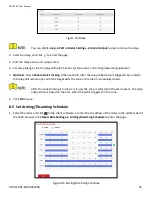
11.1
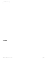
Set Time
1.
Select the radar and click
in the client software, or enter the radar IP address in the address bar of the
Web browser. Click
System
→ Time
to enter the page.
Figure 11-1 Time
2.
Set the time zone and synchronization method.
3.
Click
Save
.
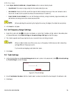
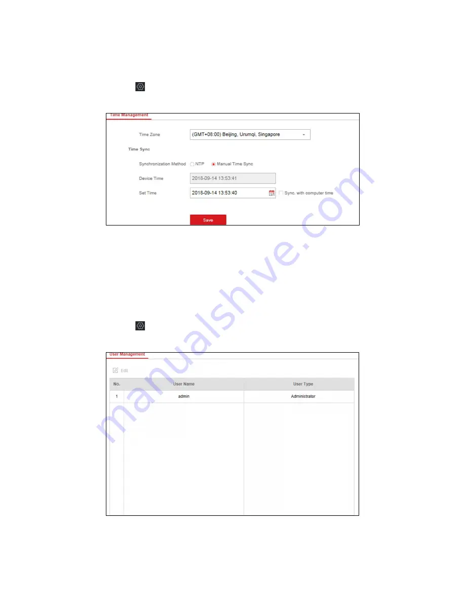
11.2
Manage User
1.
Select the radar and click
in the client software, or enter the radar IP address in the address bar of the
Web browser. Click
System
→ User
to enter the page.
Figure 11-2 User
2.
Select the admin account, and click
Edit
to edit the admin information.
Содержание DS-PR1-60
Страница 1: ...DS PR1 60 Security Radar User Manual...
Страница 32: ...DS PR1 60 User Manual UM DS PR1 60 090920NA 32 Figure 5 5 Installation Scene for One Point Calibration...
Страница 42: ...DS PR1 60 User Manual UM DS PR1 60 090920NA 42...
Страница 69: ...DS PR1 60 User Manual UM DS PR1 60 090920NA 69...
Страница 70: ...DS PR1 60 User Manual UM DS PR1 60 090920NA 70...
Страница 71: ...DS PR1 60 User Manual UM DS PR1 60 090920NA 71 UD13649B...