


DS-73xxHUI-K4, DS-73xxHQI-K4, DS-90xxHUI-K8 DVR User Manual
UM DS-73xxHUI-K4 DS-73xxHQI-K4 DS-90xxHUI-K8 092017NA
87
5.12.2.2
Playback by Time
Purpose
Play back video files recorded during a specified time duration.
Multi-channel simultaneous playback and channel switch are
supported.
1.
Go to Menu > Playback.
2.
Check the checkbox of the channel(s) in the channel list, then
double-click to select a date on the calendar.
Figure 109,
Playback Calendar
If there are record files for that camera on that day, the icon
for that day is displayed on the calendar as
. Otherwise it is
displayed as
.
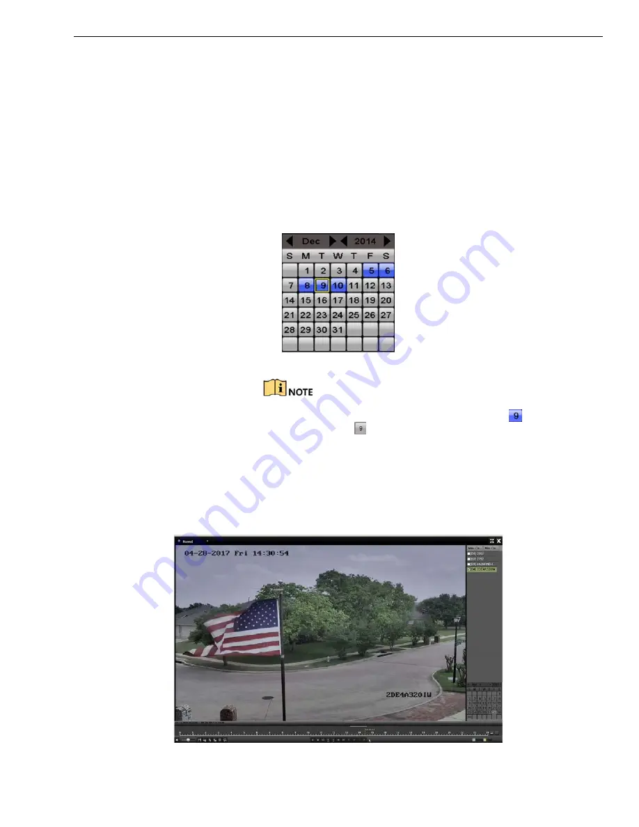
5.12.3
Playback Interface
1.
You can select main stream or sub-stream from the playback drop-down
list. You can also use the toolbar in the bottom part of
Playback
interface
to control playing progress, as shown in the following figure.
Figure 110,
Playback Interface


