background image


EN – Translation of the original user manual -  2.1 | 2019 

79 

7.16


ADDITIONAL OPTIONS FOR REL4 AND REL5  

 
The two changeover relays Rel4 and Rel5 can optionally be assigned functions 
from the following table. Contacts can also be connected to the backplane; see 
appendix B and C 

Value  

Relay output functions  

  0   No function  

  6   Status indication:  Maintenance required (cycle counter, 

maintenance interval reached) 

  7   Status Indication: Fault / error has occurred (after the recovery of 

all error messages, this relay remains active for about 2 seconds) 

11   Activation of an additional electric motor brake (relay is active when 

the motor is running) 

20   Simple traffic light control [RED / GREEN] (relay is active when the 

gate is in the OPEN position and the flash light is not active) 

21   Output for lighting [when the timer for lighting is also greater than 

0] 

(Relay is active when the flash light is active and also during the 
time set in the lighting timer) 

25  Output for safety edges. Will be active if one or more safety edges 

are activated 

27   Output for JCM NO-TOUCH: Active during the gate movement OPEN 

between gate position CLOSED and VorEnd-OPEN 

28  

Output for JCM NO-TOUCH: Active during the gate movement 
CLOSED between gate position OPEN and VorEnd-CLOSED


29   Output for JCM NO-TOUCH: Contains the two functions described 

above (depending on the direction in which the gate moves) 


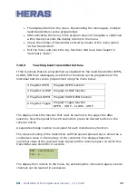
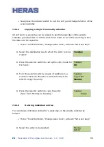
The selection in the menu is as follows: 


Содержание HGD230

Страница 1: ...2 1 2019 1 User Manual Gate with drive HMD230 HGD230 IGD230 Please read this original user manual before using this gate for the first time Act in accordance with the manual and keep it in a safe plac...

Страница 2: ...EN Translation of the original user manual 2 1 2019 2...

Страница 3: ...NCES 13 2 3 GENERAL SAFETY INSTRUCTIONS 13 2 4 SAFETY PROVISIONS EMPLOYED 14 2 5 INTENDED USE 15 2 6 SAFETY DURING USE 15 2 7 SAFETY DURING INSTALLATION MAINTENANCE AND DISASSEMBLY 16 3 OPERATION 18 3...

Страница 4: ...s events 37 5 5 5 Selecting the menu system 38 5 5 6 Menu system 38 5 5 7 Entering the password 38 5 6 MENU DISPLAY INSTRUCTIONS 40 5 7 MENU STRUCTURE TEXTS AND REFERENCES 42 5 7 1 Setting the languag...

Страница 5: ...MP YARD LIGHTING 69 7 8 PROGRAMMING SERVICE INTERVALS 70 7 8 1 Cycle counter 70 7 8 2 Motor runtime 71 7 8 3 Maintenance interval 71 7 8 4 Setting the maintenance message on a flash light 71 7 8 5 Mai...

Страница 6: ...lendar 92 7 22 2 Displaying the weekly calendar 92 7 22 3 Adding and changing entries in the weekly calendar 93 7 22 4 Copying a day in the weekly calendar 94 7 22 5 Deleting individual entries 94 7 2...

Страница 7: ...l user manual 2 1 2019 7 13 TECHNICAL DATA 110 13 1 SLIDING GATE DESCRIPTION 110 13 2 DRIVE DESCRIPTION 110 APPENDIX A DECLARATIONS DOP DOC 112 APPENDIX B ELECTRIC DIAGRAM HMD230 HGD230 115 APPENDIX C...

Страница 8: ...long term The document is the description for the use of the electric gate control HMD230S or HMD230A in the software version 2 40 40e 50 or newer In the further description the two variants are gener...

Страница 9: ...37277 Heras UK Telephone 44 0 1302 364 551 Heras France Telephone 33 0 3 88 067 000 Heras Norway Telephone 47 22 900 555 Heras Sweden Telephone 46 0 77 1506050 DEFINITIONS USER OPERATOR ENGINEER 1 3 U...

Страница 10: ...ic compatibility 305 2011 EC Construction Product Regulation The design and production has been executed compliant with the applicable product standard EN 13241 and the underlying standards EN 12604 E...

Страница 11: ...ordance with EN 60335 1 and IEC 30364 5 54 must be provided Measurement is made according to EN 60335 2 103 Consult your installer for this Take into account good shielding for example an automatic ci...

Страница 12: ...2 HGD230 cover cabinet and gear wheel IGD230 1 10 The IGD230 is delivered as a complete drive and control unit including gear wheel module 6 The drive is only delivered together with the iGate By defa...

Страница 13: ...SAFETY INSTRUCTIONS The operator must read the entire user manual before the gate is used for the first time The instructions stated in the user manual must be observed and complied with All other fo...

Страница 14: ...lation and operating instructions is not clear then please contact your supplier before you use the equipment This manual must always be available at the operating location of the control gate This ma...

Страница 15: ...op and reverse the gate movement Using them as a regular gate stop feature is not allowed Since the head stiles of the gate have safety edges that cannot cover their full height there is still some ri...

Страница 16: ...e necessary personal safety equipment The gate is driven by means of a gear wheel This is located under the beam and it is partly screened off by the drive unit cabinet Beware of moving parts when car...

Страница 17: ...EN Translation of the original user manual 2 1 2019 17 Illustration 4 Warning sticker bottom rail...

Страница 18: ...has been programmed CLOSE Press the Close button The gate closes completely STOP Press the Stop button The gate will stop immediately irrespective of its direction of travel To restart the gate press...

Страница 19: ...to the HGD230 and IGD230 3 2 3 Open close in case of emergency Two push buttons are located on the backplane of the control unit These can be used to open close and stop the gate Illustration 7 Backpl...

Страница 20: ...ase the motor 3 2 5 Engaging the motor When locking the system again close the gate as far as the mark on the bottom rail Now move the gate back and forward a bit to engage the gear wheel with the rac...

Страница 21: ...if there is a power failure can be recognized by a coil this will automatically disengage the drive if a power failure occurs Illustration 10 Automatic disengagement Attention To be able to use the e...

Страница 22: ...ouble version Applications include port areas company buildings office buildings storage sites garden and landscape areas high risk sites airports transport and distribution sites and parking garages...

Страница 23: ...nd parking garages Illustration 12 uGate sliding gate terms 4 3 IGATE The iGate is a cantilever sliding gate for openings up to 9 meters in a single version The filling consists of perforated sheeting...

Страница 24: ...enings up to 13 metres in a single version and up to 26 metres in a double version Applications include harbor areas company buildings storage sites high risk sites airports and transport and distribu...

Страница 25: ...ations include harbor areas company buildings storage sites high risk sites airports and transport and distribution sites Illustration 15 SafeGlide 2 sliding gate terms 4 6 DRIVE UNIT 4 6 1 Drive unit...

Страница 26: ...ependent on the device the gate will restart The safety edges have been fitted to the stationary and or moving part or parts of the gate They are not required for hold to run control These strips serv...

Страница 27: ...le the gate is opening closing A technician can program the switching time In some countries a flashing light is obligatory 4 9 4 Remote control optional Remote control to open stop and close the gate...

Страница 28: ...ring the right password 4 10 OPERATING MODES The control software is divided into separate function modules and is available to users in three possible operating modes hold to run mode automatic mode...

Страница 29: ...es the gate to immediately move in the opposite direction If a photocell is interrupted while the gate is closing this will cause the gate to be opened as far as the point where the closing movement s...

Страница 30: ...the command triggered by an OPEN or CLOSE command key being pressed cannot be performed when a program is started a static active Emergency situation input signal will also not be carried out when swi...

Страница 31: ...2 1 2019 31 Hold to run control mode Automatic mode if safety has been restored Automatic mode Emergency operation Emergency operation Automatic mode if no emergency situation signal is active anymore...

Страница 32: ...it 5 2 TOTAL VIEW OF HGD230 IGD230 DRIVE UNIT Illustration 17 view of IGD230 drive unit IGD230 only cable strain relief cable bushing backplane automatic fuse place for extra components motor automati...

Страница 33: ...EN Translation of the original user manual 2 1 2019 33 5 3 VIEW OF CONTROL UNIT Illustration 18 view of control unit...

Страница 34: ...rd 70 757 print 16 Antenna connection of the receiver for the hand transmitters optional 18 Socket for the receiver print optional 19 Encoder connection 5 4 TWIST AND SELECTOR SWITCH The twist and sel...

Страница 35: ...tting the software or after switching on the power the display light will blink for a few seconds This indicates that the processor is booting it is not a fault condition 5 5 1 Display of operating mo...

Страница 36: ...ay format The lower line shows the time in the 24 hour hours minutes seconds format The selected operating mode is displayed again if you briefly press the twist and selector switch or 20 seconds afte...

Страница 37: ...ISK Mov prot CLOSED Moving anti crushing safety protection device for the CLOSING direction ISK Vehicle prot Value 1 x Photocell status Sensors End Turn the selector switch in a clockwise direction to...

Страница 38: ...splay then shows the text Main menu Illustration 22 Display of main menu on the LCD screen Turn the selector switch to select the individual menu options and then press the switch to activate the sele...

Страница 39: ...ivate this menu option and to access the field where you can enter the password Enter passw Value 3XXXX Turn the switch to change the preset value shown The faster you turn the faster the values will...

Страница 40: ...sion Bootloader Motorcontroller Bootloader Peri Software version Bootloader Peripheriecontroller 2 Service Password entry Access password for authorised persons and activation extra functions Language...

Страница 41: ...r editing the registered gate functions in the weekly calendar Disp Year Cal Display of the registered gate functions in the annual calendar Edit Year Cal Editing possibility of the integrated annual...

Страница 42: ...e motor drive How many submenu levels are available depends on the password that is entered First level submenus can lead to second level submenus The colored entries in the submenus of the following...

Страница 43: ...ch 3 German 4 French 5 Norwegian 6 Swedish 7 Danish 3 Mot Rotation Chap 7 1 4 Calender choice Chap 7 22 1 5 Emergency Oper Chap 7 9 3 Diagnostics Menu back 1 Gate State Chap 7 19 3 Menu back 1 Gate st...

Страница 44: ...Temperature Chap 7 19 5 3 RESET Min Max 4 Settings Menu back 1 Set timer Menu back 1 Lighting s Chap 7 7 2 TMR Keep open Chap 7 11 1 3 TMR keep part op Chap 7 11 2 4 TMR Autom Close Chap 7 11 3 5 Sec...

Страница 45: ...ISK activation Chap 7 2 3 JCM activation Chap 7 2 1 4 JCM NTouchONLY Chap 7 2 2 5 Spec Parameter Menu back 1 Cycles to service Chap 7 8 1 2 RuntimeToService Chap 7 8 2 3 Serv Interv M Chap 7 8 3 4 Se...

Страница 46: ...time Chap 7 21 2 Menu back Year Month Day Hour Minute Second Daylight saving Now daylight 3 Cal Activation Chap 7 22 1 4 Disp Week Cal Chap 7 22 2 5 Edit Week Cal Menu back 1 Set weekdays Chap 7 22 3...

Страница 47: ...PlaceNO Chap 7 20 5 9 Delete all Chap 7 20 6 5 7 1 Setting the language After entering the password the engineer can change the menu interface language In addition to the default language English ano...

Страница 48: ...n 23 Backplane The following statements belong to the numbers which can be found in Figure 23 1 With the buttons OPEN and CLOSE the gate can be operated both deadman and in automatic mode During learn...

Страница 49: ...in the chapter Safety Avoid parallel signal and energy leads and cables where possible The dimensions of all leads and cables must be adjusted to the power consumption The Cable glands must be treate...

Страница 50: ...ons for EMC installation Attention If the installation does not comply with EMC requirements other equipment in the direct vicinity of the motor drive may be disturbed The HMD230 is a motor drive whic...

Страница 51: ...ke contact Switches with a static make contact e g timer are also allowed for the open and part open functions Contacts can also be connected to the backplane see appendix B and C Only controls with a...

Страница 52: ...tial OPEN function and at In6 an emergency stop switch 6 2 1 Installing the dead man s keys You cannot put a gate into operation until at least one OPEN and one CLOSED key have been connected for dead...

Страница 53: ...o longer possible to move the motor When the input is deactivated the program of the controller performs a reset Contacts can also be connected to the backplane see appendix B and C Switch off the pow...

Страница 54: ...ton or switch contact make contact is connected to input In5 Contacts can also be connected to the backplane see appendix B and C Switch off the power supply to the motor drive Connect the key switch...

Страница 55: ...used to connect the M8 connector or the input terminal but they cannot both be connected to the same input terminal This would result in a parallel connection of the anti crushing safety protection d...

Страница 56: ...same input at the same time is not allowed here either This would result in a parallel connection of the anti crushing safety protection device leading to failures By default the evaluation of a conn...

Страница 57: ...s This incremental encoder has been installed in the motor and supplies two square wave signals in opposite directions which the program uses to derive the necessary information The type of incrementa...

Страница 58: ...AY OUTPUT CONNECTIONS The HMD230 has five relays available for signalling and lighting purposes Illustration 25 Relays Rel1 to Rel3 are make contacts the other two relays Rel4 Rel5 are make and break...

Страница 59: ...nnected lamp The service engineer can assign one of the following functions to the relays Rel4 and Rel5 Lighting yard lighting with deactivation relay after a gate movement has ended Traffic light fun...

Страница 60: ...imum load of 250 W Only replace the fuse 6 3A slow acting by a fuse of the same rating Caution In accordance with the standards the relay outputs have been separated from the low safety voltage on the...

Страница 61: ...ore of the coax cable of the antenna is connected to the right hand terminal near the housing side The antenna shield is connected to the left hand terminal Illustration 33 Electrical connection of ra...

Страница 62: ...change the value to 1 Double check that the gate moves in the right direction 7 2 PROGRAMMING THE MOVING ANTI CRUSHING SAFETY PROTECTION DEVICES ISK The moving anti crushing safety protection devices...

Страница 63: ...HMD230 controller the hardware must be installed in accordance with the specifications supplied both for the OPEN and the CLOSE direction The wiring of a JCM radio receiver RB3R868 to the controller...

Страница 64: ...devices have been connected correctly and check the reaction of the gate in the relevant movement direction in automatic mode 7 2 2 Setting JCM No Touch System The No Touch system from JCM can also b...

Страница 65: ...for the information of the moving anti crushing device on the gate must be carefully installed adjusted and tested according to the description provided 7 3 LEARNING THE END POSITIONS OF THE GATE The...

Страница 66: ...RESET pos The total teaching procedure has to be repeated then Attention Teaching the end positions must always start by teaching the CLOSED position Other entry sequences will not be accepted Attent...

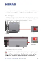
Страница 67: ...side of the drive unit If this is not the case then manually move the gate to its CLOSED position On a SafeGlide 2 no marker plate is mounted Marker plate Marker plate Illustration 37 Marker plate on...

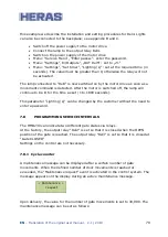
Страница 68: ...the gate will move to its OPEN end position Photocells can also be connected to the backplane see appendix B and C Photocell with normally closed contact The photocell is always factory set with a no...

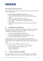
Страница 69: ...ashing light is connected to relay Rel1 as follows Lights can also be connected to the backplane see appendix B and C Switch off the power supply to the motor drive Connect the 24V power supply to out...

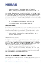
Страница 70: ...amp will continue to be lit for the time as set 1 to 1800 seconds This parameter Lighting s can be changed by the customer without the need to enter a password 7 8 PROGRAMMING SERVICE INTERVALS The HM...

Страница 71: ...intenance message can be set as follows Menu Service Menu Enter passw enter the password Menu Settings Spec parameter RuntimeToService set to a value in number of hours 7 8 3 Maintenance interval For...

Страница 72: ...onger after the OPEN or CLOSE position has been reached 2 Flash light remains switched on for 8 seconds longer 3 Flash light remains switched on for 12 seconds longer 7 8 5 Maintenance message on a re...

Страница 73: ...THE EMERGENCY SITUATION FUNCTION The emergency situation function enables the gate to be opened or closed depending on the parameters remotely by a fire emergency room without jeopardising safety For...

Страница 74: ...ed again the motor drive will perform a reset and the gate is opened again when the next command is given 7 10 Setting the traffic light A simple traffic light circuit can be created using make and br...

Страница 75: ...ctivated during this time the timer will start to count down again This value can be changed by the customer without the need to enter a password The TMR automatic closing is not activated when the ma...

Страница 76: ...nter a password Attention If a TMR AUTOMATIC CLOSING IS SET and the gate is in the OPEN position and the control is restarted for example by interrupting the voltage THE TMR AUTOMATIC CLOSING IS ALSO...

Страница 77: ...d active port functions in the controller s calendar can be temporarily deactivated by hardware switch For this purpose one of the inputs In5 or In6 can be configured to deactivate the calendar functi...

Страница 78: ...ion in the menu is as follows Connect a button or switch tot he required input In5 or In6 Menu Service Menu Enter passw enter the password Menu Settings In Outputs In5 or In6 set to a value from the a...

Страница 79: ...when the motor is running 20 Simple traffic light control RED GREEN relay is active when the gate is in the OPEN position and the flash light is not active 21 Output for lighting when the timer for l...

Страница 80: ...can restore the previously saved parameter settings so that the parameters are correct again Menu Service Menu Enter passw enter the password Menu Settings Param Backup activate Save new 7 17 2 Resto...

Страница 81: ...isplayed You can now remove the card to which data has been written and which has been checked from the card reader Attention If a chipcard reader is not connected or if errors occur during copying th...

Страница 82: ...d by the software when the chipcard is removed The HMD230 shows Init Clear EEPROM and then Load Parameter The contents of a card have to be read then again The motor drive does not work without correc...

Страница 83: ...ern as identified OPEN CLOSE StartActive Value 01000010 E g the In the displayed message for example the input In7 dead man button CLOSE has been active at start up After a change of the relevant sign...

Страница 84: ...number of movements since the last maintenance are displayed One movement is one OPEN CLOSED cycle Last Service 2011 02 24 1 mo The date of the last maintenance is displayed as well as the time that h...

Страница 85: ...n Menu Diagnosis Temp measured activate RESET Min Max This sets the minimum and maximum values of the items displayed in question to the current temperature 7 19 6 Log system The log system is a ring...

Страница 86: ...motor drive features a slot for a radio frequency receiver module An 868 MHz receiver module with FM modulation is used and the constant share of the Rolling Code of the HERAS transmitter used is anal...

Страница 87: ...ory of the motor drive for each hand transmitter The total number of transmitters stored can be displayed by means of the menu option Active transmitters Menu Remote control activate Active transmitte...

Страница 88: ...be programmed using the menu below 3 Prog But OPEN Program OPEN function 4 Prog But CLOSE Program CLOSE function 5 Prog Part OPEN Program PART OPEN function 6 Prog But Toggle Program Toggle function...

Страница 89: ...means of the menu option Active transmitters 7 20 5 Deleting memory location If a specific radio remote control or a special button of a transmitter from the memory of the controller is to be deleted...

Страница 90: ...ollows Menu Clock Calendar activate Display clock 7 21 2 Setting the clock The internal clock of the HMD230 has been factory set If this time ever differs from the actual current time the clock can be...

Страница 91: ...otor drive must be enabled by the engineer once and is then available to the customer Otherwise the calendars will not be visible Possible calendar functions actions that the motor drive can perform v...

Страница 92: ...sponding functions gate actions can be entered in the weekly calendar for every individual week day Sunday through Saturday Only the times entered are shown in the display mode for the weekly calendar...

Страница 93: ...ion to select the hour for the switching time Monday 12 Press the selector switch to call up the entry mode for the minutes Monday 12 00 Turn the selector switch in a clockwise direction to select the...

Страница 94: ...week days Select the destination day to which the entry is to be copied Tuesday Press the selector switch to call up the entry mode for the hours Tuesday 00 Turn the selector switch a couple of posit...

Страница 95: ...ing the first entry for the week day in question Menu Clock Calendar Change week clock activate Set week days Select the first entry of the week day to be deleted Monday 08 00 Hold open If you turn th...

Страница 96: ...pty memory positions are skipped The yearly calendar can be displayed as follows Menu Clock Calendar select Display year clock Switching date 2018 09 30 12 30 No action Switch time Function Gate actio...

Страница 97: ...he selector switch in a clockwise direction to select the day 2019 06 17 Press the selector switch to call up the entry mode for the hours 2019 06 17 00 Turn the selector switch in a clockwise directi...

Страница 98: ...ly to all entries for this day The yearly calendar is sorted i e an older date is put before a more recent date 7 22 10 Copying a day in the yearly calendar All entries for a certain day can be copied...

Страница 99: ...endar Ready 7 22 12 Deleting a day You can also delete all entries for an individual day from the yearly calendar after selecting the first entry for the day in question Menu Clock Calendar Change yea...

Страница 100: ...a signal lamp to realy output Rel5 Switch on the power supply to the motor drive Menu Service Menu Enter passw enter the password Menu Settings In Outputs OUT Rel5 set to 7 The lamp that is connected...

Страница 101: ...ight This can also be done automatically using a light dark switch When darkness falls the lights on the gate will go on See the manuals for the LED control unit and the week timer for instructions on...

Страница 102: ...ctivated a 0 is stored directly behind the text if the motor was not active 26 Stat safety CLOSE Stationary anti crushing safety protection device CLOSE has been activated a 0 is stored directly behin...

Страница 103: ...d 143 Auto close ON After a reset of the control the gate is in the OPEN position and expects activation of the timer 155 Calendar A command has been carried out due to an entry in a calendar 161 Dire...

Страница 104: ...g error serious exception error 209 WDG reset The motor controller was restarted by the watchdog 210 MotRunTimeError The motor movement was stopped because the maximum motor run time for this gate mov...

Страница 105: ...on of the enable signal 230 REL error Idl The stationary voltage value measured by the voltage monitoring function of the enable signal was too high 234 INC sensor OP Incorrect value from the encoder...

Страница 106: ...inter error 250 ProgramInit In the system log the program has been initialized clear and initialize the parameter memory In the events log the program was restarted e g reset at Exit menu 251 EMERGENC...

Страница 107: ...requent maintenance checks are recommended during the lifetime of the gate Any maintenance work including repair replacement modification and upgrade MUST be conducted by a Heras trained qualified com...

Страница 108: ...ind the operating company user of this necessary maintenance the MAINTENANCE necessary message is generated by the software of the motor drive 10 3 CLEANING The gate and the outside of the drive unit...

Страница 109: ...e This can lead to serious injury Therefore it is prohibited to disassemble the bottom rail yourself Only people trained by Heras are allowed to disassemble the bottom rail There is no hidden danger a...

Страница 110: ...disengagement Supply voltage VAC 1 phase 230VAC N PE 10 50 60Hz External power supply 230V 230VAC 10 50 60Hz fused with a 6 3A slow acting fuse on the PCB Internal power supply 24V 24VDC stabilized 5...

Страница 111: ...EN Translation of the original user manual 2 1 2019 111 Weight kg 22 26 The functions described in this manual are designed for the prevailing climatic conditions in Europe...

Страница 112: ...EN Translation of the original user manual 2 1 2019 112 Appendix A Declarations Dop DoC...

Страница 113: ...EN Translation of the original user manual 2 1 2019 113...

Страница 114: ...EN Translation of the original user manual 2 1 2019 114...

Страница 115: ...EN Translation of the original user manual 2 1 2019 115 Appendix B ELECTRIC DIAGRAM HMD230 HGD230...

Страница 116: ...EN Translation of the original user manual 2 1 2019 116...

Страница 117: ...EN Translation of the original user manual 2 1 2019 117...

Страница 118: ...EN Translation of the original user manual 2 1 2019 118...

Страница 119: ...EN Translation of the original user manual 2 1 2019 119...

Страница 120: ...EN Translation of the original user manual 2 1 2019 120...

Страница 121: ...EN Translation of the original user manual 2 1 2019 121...

Страница 122: ...EN Translation of the original user manual 2 1 2019 122...

Страница 123: ...EN Translation of the original user manual 2 1 2019 123...

Страница 124: ...EN Translation of the original user manual 2 1 2019 124...

Страница 125: ...EN Translation of the original user manual 2 1 2019 125...

Страница 126: ...EN Translation of the original user manual 2 1 2019 126...

Страница 127: ...EN Translation of the original user manual 2 1 2019 127...

Страница 128: ...EN Translation of the original user manual 2 1 2019 128...

Страница 129: ...EN Translation of the original user manual 2 1 2019 129 Appendix C ELECTRIC DIAGRAM IGD230...

Страница 130: ...EN Translation of the original user manual 2 1 2019 130...

Страница 131: ...EN Translation of the original user manual 2 1 2019 131...

Страница 132: ...EN Translation of the original user manual 2 1 2019 132...

Страница 133: ...EN Translation of the original user manual 2 1 2019 133...

Страница 134: ...EN Translation of the original user manual 2 1 2019 134...

Страница 135: ...EN Translation of the original user manual 2 1 2019 135...

Страница 136: ...EN Translation of the original user manual 2 1 2019 136...

Страница 137: ...EN Translation of the original user manual 2 1 2019 137...

Страница 138: ...EN Translation of the original user manual 2 1 2019 138...

Страница 139: ...EN Translation of the original user manual 2 1 2019 139...

Страница 140: ...EN Translation of the original user manual 2 1 2019 140...

Страница 141: ...EN Translation of the original user manual 2 1 2019 141...

Страница 142: ...EN Translation of the original user manual 2 1 2019 142...

Страница 143: ...EN Translation of the original user manual 2 1 2019 143...

Страница 144: ...EN Translation of the original user manual 2 1 2019 144...

Страница 145: ...EN Translation of the original user manual 2 1 2019 145...

Страница 146: ...Local supplier stamp...

Отзывы: