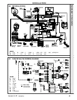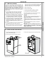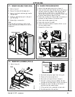
43
Henrad CC FF
- Installation
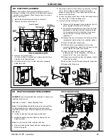
68 PUMP REPLACEMENT
Note.
The Grundfos 15/60 pump is available in several
versions, according to the position of the electrical connector
in relation to the pipework. Check that you have the correct
version - see step 9.
1. Isolate the electrical supply. Refer to Frame 54.
2. Remove the boiler bottom panel.
SER
VICING
SERVICING
3. Remove the controls panel.
If a timer is fitted it is necessary to disconnect the timer
harness at the terminal block.
4. Close the valves on the CH flow and return pipework
below the boiler.
5. Drain down (refer to Frame 68) by opening the CH drain
cock. Do not release system pressure using the
pressure relief valve as it may cause debris within the
system to foul the valve.
6. Loosen the pump outlet union and the inlet connection at
the rear of the CH return isolating valve.
7. Unplug the inline electrical connector.
8. Disconnect the pipework fully and remove the old
pump, together with the short inlet pipe.
9. Ensure that the replacement pump has the motor
positioned so that the
electrical connections are
on the same side as the inlet pipe. If necessary,
use an Allen key to remove the motor and
reposition it.
10. Transfer the short inlet pipe to the
inlet side of the
replacement pump, using a new sealing washer.
11. Make the electrical connections.
12. Offer the pump / pipe assembly to the boiler,
using the second new washer on the pump outlet
union. Tighten the water connections.
13. Close the drain cock and open the system
isolating valves. Fit the filling loop - fill, vent and
pressurise to 1 bar (or as required).
14. Restore services and operate the heating controls
to test-fire the boiler.
15. Vent air and top up the pressure again, if required.
16. Remove the filling loop.
WARNING. This will necessitate disconnection of all services,
including the flue turret.
Refer also to Frame 7 - 'Boiler Exploded View'.
Note.
If the installation allows the boiler to be removed from
the pre-piping frame the replacement will be more easily
conducted if this is done. If this is possible remove the boiler
after step 6.
1. Isolate the electrical and gas supply to the boiler.
2. Isolate the water and gas supplies by closing 3 cocks
below the boiler.
Note.
Do not close the DHW restrictor ball valve.
3. Remove the boiler front panel and inner sealing panel.
Refer to Frame 48.
69
HEAT EXCHANGER REPLACEMENT

