


49
Henrad CC FF
- Installation
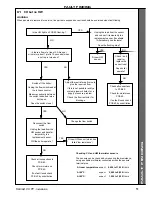
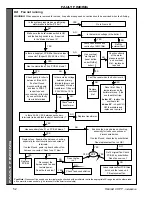
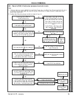
79 FAULT FINDING MAIN MENU
F
AUL
T FINDING
FAULT FINDING
YES but only
briefly
No pressure
or
wrong pressure
NO
Does the boiler light ?
Is there a spark at the ignition electrodes
during an ignition attempt ?
Go to Frame 84
Has the gas line been purged of air ?
Purge gas line
Can the correct burner pressure be
measured during an ignition attempt (i.e.
when PCB 37 LED2 goes OFF briefly) ?
Go to Frame 83
NO
Does the fan run correctly ?
NO
Is the water system pressure low ?
Go to Frame 82
NO
Go to Frame 86
YES
YES
NO
YES
NO
Does the boiler provide CH ?
Does the boiler provide HW ?
Go to Frame 81
Go to Frame 80
Does the boiler provide CH ?
YES
YES
Go to Frame 85
NO
NO
Correct
pressure
YES
EXIT
YES
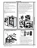
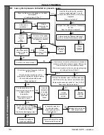
START THE BOILER FROM COLD
The correct sequence of operation during ignition is as
follows:-
1. Mains to boiler with water pressure switch and overheat
thermostat closed.
2. a. Hot water tap turned on (HW and Fan lights come on) -
the flow switch signals this to PCB 40, which starts the
fan at full speed and sends power to Ignition Control
PCB 37 via the casing pressure switch.
or b. Clock, heating switch and room thermostat call for
heat (CH and Fan lights come on) - PCB 40 senses
this, starts the fan at full speed and sends power to the
pump and Ignition Control PCB 37, via the casing
pressure switch.
or c. Both the above call for heat (HW and Fan lights come
on) - HW takes priority, i.e. pump OFF, fan running at
full speed, power to PCB 37.
3. If the fuse on PCB 37 is OK, the 'power' and 'lockout' LEDs
PCB 37 illuminate.
4. After 8 seconds pre-purge time 'lockout' LED 2 goes OFF,
the spark starts and the gas valve opens.
5. If a flame is detected the spark stops, 'lockout' LED stays
OFF and the 'Burner on' neon lights - the fan speed and
gas rate then adjust as dictated by boiler water
temperature.
6. If a flame is not detected the spark stops, the gas valve
closes, the fan continues to run and 'lockout' LED comes
ON.
Foot Note: Presence of Live supply on a terminal may be
checked with a multimeter set to the appropriate AC range
(apply the other probe of the meter to mains neutral, e.g. on
terminal N of the timer terminal strip).
WARNING. No part of the boiler should be touched without
first isolating the mains supply.
Note.
Switching the boiler on/off switch 'off' when a frost thermostat is wired
directly from the mains may leave a live feed to the boiler.