background image

15

Henrad CC FF 

- Installation

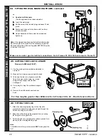
13 DRILLING THE WALL (Rear Flue)

IMPORTANT

. Ensure that, during the cutting operation,

masonry falling outside the building does not cause damage or
personal injury.

1. Cut the flue hole (preferably with a 5" core boring tool),

ensuring that the hole is square to the wall.

2. Measure and note the wall thickness 'W'.

3. Drill the 6 fixing holes with an 8mm (

5/16

") masonry drill.

Note. 

If the terminal is to be sited within 25-40mm of a

corner or vertical pipe (refer to Table 5) then the hole MUST
be accurately cut and the rubber weather seal trimmed
around the groove provided.

(The terminal wall plate cannot be fitted close to a corner).

11

REAR FLUE ASSEMBLY - Exploded View

12 WALL MOUNTING TEMPLATE (Rear Flue)

IMPORTANT.

For direct mounting (wall mounting frame on wall) choose
one black dot in each group.

If using the stand-off channels choose one dotted circle in
each group. Care MUST be taken to ensure the correct
holes are drilled.

1. Tape the template into the selected position.

2. Ensure squareness by hanging a plumbline as shown.

3. Mark onto the wall the following:

a.

The 6 wall mounting plate screw positions.

b.

The position of the flue duct.

LEGEND

1. Terminal.

2. Weather seal.

3. Duct assembly.

4. Sealing ring.

5. Clamping ring.

6. No.8 x 8 self tapping screw.

7. Flue turret.

8. M5 x 10 pozi Hex screw.

9. Turret clamp.

INSTALLATION

REAR FLUE OUTLET

Mark the centre of the hole as well as the circumference.

4. Remove the template from the wall.

Содержание CC 100 FF

Страница 1: ......

Страница 2: ...2 Henrad CC FF Installation CAUTION To avoid the possibility of injury during the installation servicing or cleaning of this appliance care should be taken when handling edges of sheet steel components ...

Страница 3: ... CC 100 FF CC 120 FF Average flue temp mass flow rate 235 o C 11 8 g s 235 o C 14 7 g s 235 o C 14 7 g s Max DHW water inlet pressure bar lb in2 10 0 145 0 10 0 145 0 10 0 145 0 Min DHW water inlet pressure bar lb in2 1 0 14 1 2 17 1 2 17 Dry lift weight kg lb 50 110 51 2 112 51 2 112 Water content Central heating litre gal 1 7 0 37 1 7 0 37 1 7 0 37 Domestic hot water litre gal 0 48 0 11 0 7 0 15...

Страница 4: ... flow temperature of 60 o C The boiler casing is of white painted mild steel with a drop down controls access door The boiler temperature control is located behind the controls access door The heat exchanger is made of copper and cast iron The system pipework must include drain cocks in appropriate places Pipework may be taken downwards or upwards behind the boiler using the stand off channels OPT...

Страница 5: ...iler is then directed by the automatic switching off of the circulation pump to heat the inner coils and supply a maximum draw off of CC 80 FF 9 6 l min 2 1 gpm at 35 0 rise CC 100 FF 12 0 l min 2 6 gpm at 35 0 rise CC 120 FF 14 4 l min 3 1 gpm at 35 0 rise The nominal DHW temperature is 60 o C but water drawn off when the boiler has been on for central heating may be hotter than this for a short ...

Страница 6: ...e into which the boiler is going to be installed is less than the length of flue required the flue must be fitted from the outside Installation from inside ONLY b If a core boring tool is to be used inside the building the space in which the boiler is to be installed must be at least wide enough to accommodate the tool Boiler connections are made on the mounting frame Refer to Frame 17 Distance X ...

Страница 7: ...ed and serviced by a CORGI registered installer identified by in accordance with the above regulations Failure to install appliances correctly could lead to prosecution It is in your own interest and that of safety to ensure the law is complied with The installation of the boiler MUST also be in accordance with the latest I E E BS 7671 Wiring Regulations local building regulations bye laws of the ...

Страница 8: ...t the guard is fitted centrally 5 Where the terminal is fitted within 850mm 34 of a plastic or painted gutter or 450mm 18 of painted eaves then an aluminium shield at least 750mm 30 long should be fitted to the underside of the gutter or painted surface fitted centrally above the flue 6 The air inlet products outlet duct and the terminal of the boiler MUST NOT be closer than 25mm 1 to combustible ...

Страница 9: ...Working Pressure All components of the system must be suitable for a working pressure of 3 bar 45 lb in2 and temperature of 110 C Extra care should be taken in making all connections so that the risk of leakage is minimised The following components are incorporated within the appliance a Circulating pump b Safety valve with a non adjustable pre set lift pressure of 3 bar 45lb in2 c Pressure gauge ...

Страница 10: ... boiler and drain the system while still hot Refill and vent the system Re pressurise the system to the desired charge pressure see the table below 6 Size of expansion vessel For the system water expansion to be contained by the 8 litre expansion vessel fitted to the boiler the cold system volume must not exceed 119 litres when pressurised to 0 5 bar cold 107 litres when pressurised to 0 7 bar col...

Страница 11: ...mperature o C 11 11 differential o F 20 20 Head available for m w g 2 75 2 5 system pump pos 3 ft w g 9 0 8 0 Water Flow Rate and Pressure Loss 9 Draining the system Draining taps MUST be located in accessible positions to permit the draining of the whole central heating system including the central heating side of the boiler The taps should be at least 1 2 BSP nominal size and be in accordance wi...

Страница 12: ...pipe 29 30 EMC filter 32 CH Return pipe assy 33 Pump pipe assy 34 CH Lower flow pipe assy 35 CH Upper flow pipe assy 36 DHW Upper cold pipe assy 37 DHW Upper hot pipe assy 38 DHW Lower cold pipe assy 39 DHW Lower hot pipe assy 40 Boiler front panel 41 Sealing panel 44 Tank cover assy 45 Controls door assy 59 Turret clamp 67 Transformer 9 PCB 8 Fan speed controller 11 Boiler overheat t stat 12 Wate...

Страница 13: ...dard flue assembly for lengths up to 600mm rear or side flue outlet in Pack B1 Unpack and check the contents Boiler Pack Contents The boiler These Installation Servicing Instructions The User s Instructions Wall mounting template Wall mounting frame 1 pair stand off channels optional use Flue turret Clamping and sealing ring Mains connector assy Hardware Pack Coupling Hardware Pack Hardware Pack M...

Страница 14: ...bow 4000mm maximum for the 100 and 120 only Calculate the total length of flue by the following Rear flue length Dim W 79mm 3 1 8 Rear flue length with stand off channels Dim W 109mm 4 3 8 RHS flue length Dim R 220mm 8 5 8 LHS flue length Dim L 96mm 3 3 4 Note These figures include the length of flue entering the flue turret socket USE A MAXIMUM OF 3 EXTENSION DUCTS ONLY FOR THE 80 AND A MAXIMUM O...

Страница 15: ...be fitted close to a corner 11 REAR FLUE ASSEMBLY Exploded View 12 WALL MOUNTING TEMPLATE Rear Flue IMPORTANT For direct mounting wall mounting frame on wall choose one black dot in each group If using the stand off channels choose one dotted circle in each group Care MUST be taken to ensure the correct holes are drilled 1 Tape the template into the selected position 2 Ensure squareness by hanging...

Страница 16: ...o the wall plugs and leave 10mm proud Hang the frame onto the screws and tighten up or b Use stand off channels To allow pipework to be taken upwards Insert wall plugs Put the screws into the wall plugs and leave 10mm proud Fasten each channel to the frame with the 6mm screws provided Hang the channels and frame onto the screws and tighten up Note If the clearances above and below the boiler are l...

Страница 17: ...Remove the cardboard support and any burrs For flue lengths greater than 600mm 23 5 8 refer to Frames 30 to 32 Flue Extension Ducts 16 FITTING THE FLUE 1 Attach the clamping sealing rings to the flue this prevents the assembly being pushed right through the hole and causing an accident 2 Pass the cut flue through the prepared hole ensuring that the groove is uppermost 3 Pull the flue back to compr...

Страница 18: ...rame 39 2 WARNING Ensure that the plastic plugs are removed from both the DHW and CH pipes before mounting N B Some spillage of water may occur from the pipework when mounting the boiler to the frame 3 Lift the boiler onto the wall mounting frame locating it over the tabs at the top of the frame 4 Lower the boiler into position 5 Remove the bottom panel to access service connections 6 CC 80 FF onl...

Страница 19: ... neatly or c When the wall face is rough and the rubber seal on its own would be ineffective 1 Position the terminal wall plate over the terminal 2 Drill 4 fixing holes with a 7mm 1 4 masonry drill 3 Insert the 4 plastic plugs provided in flue pack B 4 Secure the plate with 4 of the No 10 x 2 screws provided in flue pack B Note If the terminal is less than 2m 6 6 above ground level an approved ter...

Страница 20: ...fer to Frame 10 1 Tape template into the selected position 2 Ensure squareness by hanging a plumbline as shown 3 Mark onto the wall the following a The 6 wall mounting plate screw positions choose one from each group b Extended the centre line as shown Mark the flue duct centre from the corner see diagram and template Note Mark the centre of the hole as well as the circumference 4 Remove template ...

Страница 21: ...l is to be sited within 25 40mm of a corner or vertical pipe refer to Table 3 then the hole MUST be accurately cut and the rubber weather seal trimmed around the groove provided The terminal wall plate need not be fitted IMPORTANT Ensure that during the cutting operation masonry falling outside the building does not cause damage or personal injury 1 Cut the flue hole preferably with a 5 core borin...

Страница 22: ...me with the 6mm screws provided Hang channels and frame onto the screws and tighten up Note If the clearances above and below the boiler are less than the length of the pipes it will be necessary to position the pipes behind the wall mounting plate BEFORE the plate is screwed to the wall Flues up to 600mm 23 5 8 1 Attach the clamping sealing rings to the flue this prevents the assembly being pushe...

Страница 23: ...and long wood screw INSTALLATION SIDE FLUE OUTLET 1 The boiler may be prewired to the loose electrical connector and secured with the cable clamps Refer to Frame 39 2 WARNING Ensure that the plastic plugs are removed from both the DHW and CH pipes before mounting N B Some spillage of water may occur from the pipework when mounting the boiler to the frame 3 Lift the boiler onto the wall mounting fr...

Страница 24: ... neatly or c When the wall face is rough and the rubber seal on its own would be ineffective 1 Position the terminal wall plate over the terminal 2 Drill 4 fixing holes with a 7mm 1 4 masonry drill 3 Insert the 4 plastic plugs provided in flue pack B 4 Secure the plate with 4 of the No 10 x 2 screws provided in flue pack B Note If the terminal is less than 2m 6 6 above ground level an approved ter...

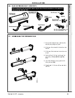
Страница 25: ...flue duct 3 Fit the outer flue extension duct onto the outer air duct 4 Drill one 3 2mm 1 8 dia hole through the outer air duct Do not drill the inner flue duct 5 Insert the self tapping screw provided to fix the air duct in position 6 Repeat steps 1 5 if a second flue extension is required INSTALLATION INSTALLATION Use a maximum of 3 extension ducts only for the 80 and a maximum of 4 extension du...

Страница 26: ...TO THE TURRET 1 Insert the flue into the prepared hole Refer to Frame 26 for details 2 Mate the flue to the turret Refer to Frame 28 for details Note To facilitate turret fixing or removal do NOT make good the wall 32 CUTTING THE FLUE TO LENGTH 34 SERVICE CONNECTIONS General Notes 1 As detailed in Frames 14 and 23 24 Fitting the Wall Mounting Frame top entry pipework is an option as well as mounti...

Страница 27: ...xtend a gas supply pipe of not less than 22mm O D copper or 3 4 BSP iron to the boiler A working gas pressure of 20mbar 8 w g must be available at the boiler inlet with the boiler firing at full DHW output INSTALLATION DHW CONNECTIONS CH CONNECTIONS For central heating loads greater than 60 000 BTUs the flow and return circuits should be increase to 28mm pipe diameter immediate y upon leaving the ...

Страница 28: ... the connector to the panel with the screw Incoming mains wiring detail INSTALLATION INSTALLATION WARNING This appliance MUST be efficiently earthed A mains supply of 230 V 50 Hz is required The fuse rating should be 3 A All external controls and wiring MUST be suitable for mains voltage Wiring should be 3 core PVC insulated flexible cord NOT LESS than 0 75 mm2 24 x 0 2mm and to BS 6500 Table 16 0...

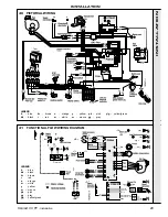
Страница 29: ...black br brown r red o orange w white y yellow m mauve pk pink gy grey y g yellow green LEGEND b blue bk black br brown r red o orange w white y yellow m mauve pk pink gy grey y g yellow green 41 FUNCTIONAL FLOW WIRING DIAGRAM INSTALLATION INSTALLATION Timer Timer kit ...

Страница 30: ...erving only the boiler and system controls The means of isolation must be accessible to the user after installation Internal Timer The Henrad Timer Kit is supplied with its own instructions Associated controls should be wired as shown in Diagram A External Single Channel Timer This should be wired as shown in Diagram B External Two Channel Timer This should be wired as shown in Diagram C The power...

Страница 31: ...st 20 mbar when the boiler is firing 13 Set the boiler on off switch C to OFF 14 Remove the pressure gauge and tube Replace the sealing screw in the pressure test point Ensure a gas tight seal is made 15 Refit the boiler front panel using the screw previously removed 16 Switch the boiler on again IMPORTANT Before lighting the boiler you should note especially that a To extract maximum heat from th...

Страница 32: ...hield valves be set a half turn open and the bypass a half turn to one turn open a minimum of one turn open is recommended when TRVs are used Make minor adjustments to each radiator to achieve the same differential on all Lastly set the bypass to eliminate any boiler noise without compromising radiator temperatures 5 Finally set the system controls to the user s requirements 6 Remove the labels fr...

Страница 33: ...ce cock and disconnect the electricity supply 2 Remove the screw and lift off the boiler front panel SERVICING SERVICING To ensure the continued safe and efficient operation of the appliance it is recommended that it is checked at regular intervals and serviced as necessary The frequency of servicing will depend upon the installation condition and usage but should be carried out at least annually ...

Страница 34: ... renew as necessary Refer to Frame 65 for replacement Note Always take care when handling the fan in order to preserve the balance of the impeller 50 BURNER REMOVAL AND CLEANING 6 Check the spark and electrode gaps are correct 7 Check that the spark and detection leads are in good condition and renew as necessary 1 After removing the fan as already described disconnect the 2 ignition leads and one...

Страница 35: ...e boiler models Frame 45 Gas rate Note that the pressure is set by the gas valve according to fan speed which in turn is controlled by reference to boiler temperature and mode CH HW thus the burner pressure should be checked at maximum demand for CH or HW as appropriate Frame 82 deals with possible causes of incorrect burner pressure 52 RE ASSEMBLY 5 Refit the fan venturi and sensing pipe assembly...

Страница 36: ...em to foul the valve 6 Disconnect the plug in lead from the temperature sensor and unscrew the sensor to release it 7 Screw in the new sensor using thread sealant reconnect and re assemble in reverse order 8 Open cock s and refill repressurise pipework 9 Test fire the boiler 10 Disconnect the filling loop if used SERVICING SERVICING 1 Disconnect the electrical supply 2 Remove the boiler front pane...

Страница 37: ...ge subpanel and allow the panel to move to one side 4 Disconnect the leads from the overheat stat Undo the clamping nut to release the stat head 5 Undo the screw and clamp securing the pancake sensing end of the thermostat to the pipe 6 Replace with new thermostat Re assemble and rewire in reverse order electrical polarity is immaterial 1 Disconnect the electrical supply to the boiler Remove the e...

Страница 38: ...er taking care not to damage the electrodes 6 Remove the spark and detection electrodes Refer to Frame 58 7 Remove the 3 securing screws and withdraw the burner from the mounting flange 8 Fit the new burner replacing any damaged or deteriorating gasket 9 Re assemble in reverse order Note Check the spark and detection gaps 61 BURNER INJECTOR REPLACEMENT SERVICING SERVICING 1 Refer to Frame 48 2 Uns...

Страница 39: ... Remove the 2 securing screws from the pressure gauge sub panel 6 Gently ease the pressure switch housing out of the pressure switch sensing hose 7 Unplug the electrical leads from the gas valve 8 Undo the gas cock union connection 9 Undo the 2 extended nuts retaining the gas injection pipe and withdraw the pipe taking care not to lose the O ring seal Undo the third nut and the gas outlet manifold...

Страница 40: ...controls panel 4 Close the isolating valves on the CH flow return at the base of the boiler then release CH system pressure by opening one of the CH drain cocks on the isolating valves It is not advisable to release system pressure using the safety valve SERVICING SERVICING 10 Supporting the valve undo the 4 retaining screws and withdraw the gas valve leaving the plate with the 3 studs in place 11...

Страница 41: ...ke care when handling the fan in order to preserve the balance of the impeller 6 Fit the new fan ensuring that a All seals are correctly refitted b The sensing pipe is correctly refitted c The fan is fully engaged 7 Check the operation of the new fan SERVICING SERVICING 65A FLOW RESTRICTOR CLEANING REPLACEMENT The restrictor is a plastic piece fitted between the lower and upper cold pipe assemblie...

Страница 42: ... made non interchangeable If in doubt refer to Frame 40 Pictorial Wiring 8 Re assemble in reverse order 9 Test both DHW and CH modes of operation 1 Disconnect the electrical supply to the boiler 2 Remove the front and sealing panels Refer to Frame 48 3 Close the isolating valve on the HW supply then release pressure by opening a hot tap Note Ensure valve markings are as shown 4 Drain using the dra...

Страница 43: ...he same side as the inlet pipe If necessary use an Allen key to remove the motor and reposition it 10 Transfer the short inlet pipe to the inlet side of the replacement pump using a new sealing washer 11 Make the electrical connections 12 Offer the pump pipe assembly to the boiler using the second new washer on the pump outlet union Tighten the water connections 13 Close the drain cock and open th...

Страница 44: ...together with the screw securing the turret to the flue pipe Remove the turret 7 Remove the fan venturi and sensing pipe Refer to Frame 49 8 Unscrew and remove the HW expansion vessel 9 Undo the 2 extended nuts securing the gas injection pipe and remove 10 Disconnect the spark electrode leads and the flame sensing electrode lead at the burner base Refer to Frame 58 11 Remove the 3 screws securing ...

Страница 45: ...ntrol panel 6 Compress the clips on the sides of the timer and withdraw it from the retaining bracket 7 Fit the new timer and re assemble in reverse order 8 Check the operation of the new timer 72 WATER PRESSURE SWITCH 1 Disconnect the electricity supply Refer to Frame 54 2 Close the CH flow and return isolating valves at the bottom of the boiler Use the drain points on these valves to release sys...

Страница 46: ...locating pin and hole are correctly positioned 76 MAINS TRANSFORMER REPLACEMENT 1 Isolate the electrical supply to the boiler Refer to Frame 54 2 Remove the boiler front panel Refer to Frame 48 3 Release the screws securing the PCB cover and remove the cover 4 Disconnect the transformer electrical leads at the in line connector 5 Release the transformer mounting screws 6 Fit the replacement transf...

Страница 47: ...g controls to test fire the boiler 11 Vent air and top up the pressure again as required 12 Remove the filling loop If the CH expansion vessel is faulty there are 3 options A If it has a punctured diaphragm but is otherwise leak free then it can be left in place and a new vessel added to the system external to the boiler provided it is of adequate capacity and pre charge pressure B If there is at ...

Страница 48: ...ill pressurise and test C9 Remove the filling loop B2 Drain down the boiler CH circuits using the appropriate drain cocks B3 Where RH clearance is available Unscrew the 10 screws securing the RHS panel and remove panel to gain access to expansion vessel connector Where RH clearance is not available Remove the fan refer Frame 49 and gas valve refer Frame 62 to gain access to the expansion vessel co...

Страница 49: ...essure switch or b Clock heating switch and room thermostat call for heat CH and Fan lights come on PCB 40 senses this starts the fan at full speed and sends power to the pump and Ignition Control PCB 37 via the casing pressure switch or c Both the above call for heat HW and Fan lights come on HW takes priority i e pump OFF fan running at full speed power to PCB 37 3 If the fuse on PCB 37 is OK th...

Страница 50: ...ns OK YES Is the CH light on PCB 40 flashing Check the lead to the pump Replace cap Switch off and change pump YES Is the HW light lit on PCB 40 If the boiler has been unused with mains off the pump may be stuck Remove screw cap on the pump head and turn the shaft with a screwdriver until free Does the pump now run YES NO Check all connections to PCB 40 Check for moisture on PCB 40 If no fault fou...

Страница 51: ...he switch close Reconnect the flow switch Unplug the lead from the HW sensor and transfer temporarily to a replacement sensor Will the boiler operate Fit new HW sensor which has failed low resistance Check all connections to PCB 40 Check for moisture on PCB 40 If no fault found check PCB 40 by substitution WARNING When panels are removed for service live parts are exposed so caution should be exer...

Страница 52: ...ace fuse Examine fan harness checking especially for short circuits between wires or terminals If no fault found power up board without fan harness connected Does fuse F1 blow YES NO YES EXIT YES YES Does the fan run NO Replace PCB 40 NO Is there mains voltage between primary terminals brown and blue leads of mains transformer Expect 230V 50Hz 10 YES YES Has the mains fuse F2 on PCB 40 blown Is th...

Страница 53: ...k fully open NO NO Is the gas supply pressure adequate at the appliance inlet during an ignition trial period i e when LED 2 on PCB 37 goes off NO YES Contact the gas supplier Is the supply pressure correct at the gas meter Rectify the fault and take steps to prevent recurrence NO Is there Live on the brown lead of the gas valve connector on PCB 37 during an ignition trial period Are both connecto...

Страница 54: ...trodes or leads externally to the burner YES YES NO Rectify poor connections or replace the spark generator or electrodes Remove the fan and burner assembly and reconnect spark leads to the electrode terminals Check that the gap between terminals is 4 to 5mm and that the distance to the flame strip is 7mm 1mm With gas OFF do another ignition cycle Is the spark OK now YES NO YES NO Re assemble and ...

Страница 55: ... of the burner at closest point Rectify any fault Does the boiler now run YES Is this a new installation Has any electrical work been done to the boiler or the house wiring YES Check the polarity of the incoming mains to the boiler see footnote Is this correct YES Check the polarity of the mains input to PCB 37 when the fan starts Is this correct Does the boiler now run Remove the burner assembly ...

Страница 56: ...alve free from foreign matter correctly set and in the closed position NO YES Replace safety valve and refill repressurise Fire the boiler up on CH Observe pressure gauge as system reaches temperature Does pressure reach or exceed 2 5 bars YES Recheck for leaks on pipes and radiators Unscrew the Schrader valve from expansion vessel and fit new valve e g from car tyre sales outlet Repressurise expa...

Страница 57: ... 29 Sensing pipe clamp plate 54 Fan burner mounting O ring 55 Fan O ring 56 Pressure pipe O ring 57 Gas manifold gasket 58 Gas valve gasket 68 Gas cock 1 2 74 Injector pipe O ring 75 Gas elbow O ring LEGEND 1 Burner 2 Burner injector 3 Gas valve 4 Flame sensing electrode 5 Ignition electrode 19 Fan assembly ...

Страница 58: ...58 Henrad CC FF Installation SHORT LIST OF PARTS 88 CONTROLS AREA Exploded View Legend 7 PCB 37 8 PCB 40 9 Fan speed control board 10 Spark generator assembly 30 EMC filter 67 Transformer assembly ...

Страница 59: ... 80 FF 1 075212 E01 797 CC 100 FF 120 FF 1 075213 4 Flame sensing electrode Buccleuch c w 1 off sensing electrode gasket 1 off M4 x 10 lg pozi pan hd screw 1 off M4 shakeproof washer 1 152033 5 E01 972 Ignition electrode Buccleuch c w 1 off ignition electrode gasket 1 off M4 x 10 lg pozi pan hd screw 1 off M4 shakeproof washer 1 075269 7 E00 046 PCB 37 Pactrol c w 4 off PCB stand offs 1 075174 8 E...

Страница 60: ...f M4 x 10 lg pozi hex hd screws 1 075192 43 E00 081 Boiler RH side panel assembly c w 6 off M4 x 10 lg pozi hex hd screws 1 075193 44 E00 082 Tank cover panel assembly c w 3 off M4 x 10 lg pozi hex hd screws 1 075194 45 Controls pod door assembly consisting of controls pod door counter plate Lighting Instruction Plate 2 off buffer pads E02 148 CC 80 FF 1 075261 CC 100 FF 1 075338 E02 117 CC 120 FF...

Страница 61: ...61 Henrad CC FF Installation 89 SHORT PARTS LIST 90 BOILER CASING ASSEMBLY SHORT LIST OF PARTS ...

Страница 62: ...d system specifiers For details of courses please ring 01482 498432 Caradon Plumbing Limited pursues a policy of continuing improvement in the design and performance of its products The right is therefore reserved to vary specification without notice June 2001 153 964 A05 Caradon Plumbing Ltd P O Box 103 National Avenue Kingston upon Hull HU5 4JN Registration No London 322 137 The code of practice...

Страница 63: ... our service We ll be giving away a free boiler for the five best ideas every year to be selected by our Technical Director Please complete this form using extra sheets if required and post it or fax it to us on 01482 498699 Boiler details Model Size details on control panel door Date of Installation Installer details Name Address Post Code Telephone Please include STD code How I would improve thi...

Страница 64: ...required Please send me details of Henrad Training Courses Please arrange for a technical representative to contact me Please arrange for me to join an Henrad factory tour Range guides required The Henrad Guide a specifier s and installer s introduction to the Henrad domestic boiler range The Henrad Householders Guide to assist the installer when presenting to his her customers Technical manuals r...

Отзывы: