background image


Model MPC-1L, MPC-22, MPC-554

4-1

FM06-038-B

June 2007

3-1.  INTRODUCTION


This section lists the replaceable parts of the Henny Penny  


MPC units.

3-2.  GENUINE PARTS


Use only genuine Henny Penny parts in your cabinet.  Using    


a part of lesser quality or substitute design may result in  


damage to the unit, or personal injury.

3-3.  WHEN ORDERING PARTS

         Once the parts that you want to order have been found in the    


parts list, write down the following information:


Example:   Item Number 


Part Number    

63464


Description    

Switch - Power


From data plate, list the following information:


Example:   Product Number  MPC554


Serial Number  AW001IE


Voltage 

120 Volt

3-4.  PRICES


Your distributor has a price list and will be glad to inform  


you of the cost of your parts order.

3-5.  DELIVERY


Commonly replaced items are stocked by your local    


distributor and will be sent out when your order is received.     


Other parts will be ordered, by your distributor, from Henny    


Penny Corporation.

3-6.  WARRANTY


All replacement parts (except lamps and fuses) are warranted  


for 90 days against manufacturing defects and workmanship.   


If damage occurs during shipping, notify the carrier at once    


so that a claim may be properly filed.  Refer to warranty in  


the front of the manual for other rights and limitations.


Recommended replacement parts, stocked by your distributor, 


are  indicated with 


in the parts lists.  Please use care when 


ordering recommended parts, because all voltages and varia-   


tions are marked.  Distributors should order parts based upon 


common voltages and equipment sold in their territory.

SECTION 3. PARTS INFORMATION

3-7.   RECOMMENDED 

SPARE PARTS FOR

DISTRIBUTORS

Содержание MPC-1L

Страница 1: ...TECHNICAL MANUAL Henny Penny Multipurpose Holding Cabinet Model MPC 554 Model MPC 1L Model MPC 22 FM06 038 B...

Страница 2: ......

Страница 3: ...3 Entering Password 2 1 2 4 Programming Descriptions 2 2 Section 3 MAINTENANCE 3 1 3 1 Introduction 3 1 3 2 Maintenance Hints 3 1 3 3 Control Board Replacement 3 1 3 4 Transformer Replacement 3 2 3 5...

Страница 4: ...ed power cord with the ground wire dimensioned to fail last If the supplied power cord or an existing one becomes damaged do not use it rather replace it with a known good power cord The power cord mu...

Страница 5: ...r or replacement of a part EXTENDED FRYPOT WARRANTY Henny Penny will replace any frypot that fails due to manufacturing or workmanship issues for a period of up to seven 7 years from date of manufactu...

Страница 6: ...the proper procedures Where information is of particular importance or is safety related the words DANGER WARNING CAUTION or NOTICE are used Their usage is described as follows DANGER indicates a haz...

Страница 7: ...arly define the problem or symptom and when it occurs 2 Locate the problem in the troubleshooting table 3 Review all possible causes Then one at a time work through the list of corrections until the p...

Страница 8: ...e polarity of 5 vdc to relay reference wiring diagram 3 If voltage varies from steps 1 and 2 remove power to unit pull input wires from relay and place leads of meter onto input wires Reapply power to...

Страница 9: ...t cut power to relay when the faulty relay or LED is green then replace control board but control board if control board does cut power to relay when the LED is green but unit continues to heat check...

Страница 10: ...WORD After accessing Special Programming Mode CodE displays and then 0 displays 1 Use the UP DOWN buttons once to increment the number to 1 2 Once the correct number displays press the P button to sel...

Страница 11: ...oard temperature displays 8 Outputs test 1 Use the DOWN button to toggle the heat outputs on off 2 Use the UP button to move on to the next step 3 Use the DOWN button to toggle each of the other three...

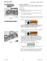
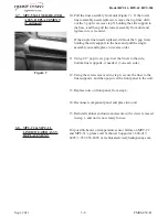
Страница 12: ...rd at wall receptacle 1 Locate the control access panel on the side of the unit and using a Phillip s head screwdriver or a 8 Torx socket re move the 2 screws securing the panel Figure 1 Slide panel o...

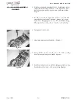
Страница 13: ...securing the control board or the buttons on the controls may not function To avoid electrical shock or property damage move the power switch to OFF and disconnect main circuit breaker or unplug cord...

Страница 14: ...power switch to OFF and disconnect main circuit breaker or unplug cord at wall receptacle 1 Slide the component panel out as described in the first step in Section 2 3 Checkout To avoid electrical sh...

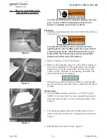
Страница 15: ...t wires from relay and place leads of meter onto input wires Reapply power to unit When unit is running if the input wires to relay shows 5vdc the relay is faulty 6 Uplug power cord to unit 7 Label an...

Страница 16: ...3 Label and remove the wires from the switch Check for continuity across the top and bottom terminals With the switch in the ON position the circuit should be closed With the switch in the OFF positi...

Страница 17: ...diagram page 2 9 and with the outputs on check across terminal 1 of the appropriate relay and the neutral wire N5 at the transformer If meter shows full voltage 120V but heater is not heating the hea...

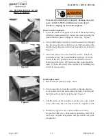
Страница 18: ...5 nuts on the rear of the front panel Figure 4 8 Using a 1 8 drill bit drill out the pop rivets securing the bottom of the front panel and then remove front panel from unit Figure 5 9 Remove the scre...

Страница 19: ...p rivets pop rivet the liners to the side bottom liner supports if needed 3 on each side 12 Using the screws removed in step 6 secure the liner to the liner supports and then pop rivet the front panel...

Страница 20: ...Model MPC 1L MPC 22 MPC 554 3 9 FM06 038 B June 2011 3 9 WIRING DIAGRAMS MPC 554...

Страница 21: ...Model MPC 1L MPC 22 MPC 554 3 10 FM06 038 B July 2011 HEATER OHM READINGS ROOM TEMP MIN NOM MAX MPC 1L 124 36 130 91 137 45 MPC 22 68 40 72 00 75 60...

Страница 22: ...u of the cost of your parts order 3 5 DELIVERY Commonly replaced items are stocked by your local distributor and will be sent out when your order is received Other parts will be ordered by your distri...

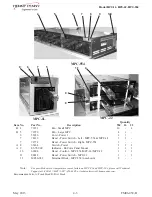
Страница 23: ...038 B July 2011 MPC 554 MPC 1L MPC 22 Item No Part No Description Quantity B 1 30978 Transformer Assembly 120VP 12VS 20VP 1 A 2 40645 Relay 25A Solid State As Required B 3 73602 Control MPC 1 Recomme...

Страница 24: ...64 Switch Power 1 1 1 A 9 LS72 000 Indicator Bi Color Panel Mount 1 1 1 10 69608 Decal Control MPC 554 MPC 1L MPC 22 1 1 1 11 88814 Decal Power Switch MPC 22 1 1 12 ME50 021 Terminal Block MPC 554 not...

Страница 25: ...er 230V 1 91996 003 Assy MPC1L Liner 100V 1 165496 001 Assy MPC1L Liner 120V 1 165496 002 Assy MPC1L Liner 230V 1 165496 003 Assy MPC1L Liner 100V 1 28979 Transformer 208 240VP 12VS 1 1 165535 001 Ass...

Страница 26: ...Henny Penny Corporation P O Box 60 Eaton OH 45320 1 937 456 8400 1 937 456 8402 Fax Toll free in USA 1 800 417 8417 1 800 417 8434 Fax www hennypenny com Revised October 2018 FM06 038 B...

Отзывы: