Model MPC-1L, MPC-22, MPC-554
3-5
FM06-038-B
Sept. 2007
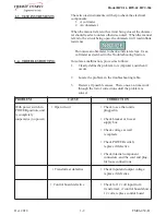
3-6. POWER SWITCH & LED
REPLACEMENT
Figure 1
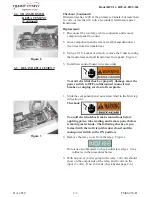
Figure 2
To avoid electrical shock or property damage, move the
power switch to OFF and disconnect main circuit
breaker, or unplug cord at wall receptacle.
Power Switch Checkout:
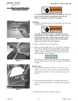
1. Locate the small access panel on the side of the unit and using
a Phillip’s-head screwdriver, loosen the screw securing the
panel and allow panel to hang out of the way. Figure 1.
2. Using a flat-blade screwdriver, insert the screwdriver through
the side access and press on the power switch mounting tabs,
and then pull the power switch out from the front of the unit.
Figure 2.
3. Label and remove the wires from the switch. Check for
continuity across the top and bottom terminals. With the
switch in the ON position, the circuit should be closed.
With the switch in the OFF position, the circuit should be
open. If the switch is defective, replace it by installing new
switch in reverse order.
LED Replacement
1. Remove access panel per step 1 above.
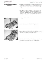
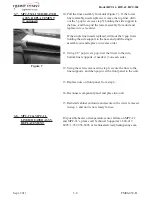
2. Using a nut-driver, insert the nut-driver through the side
access and remove the nut securing the light, and then pull
the light out from the front of the unit. Figure 3.
3. Pull the wires out far enough to reach the wire nuts. Label
wires and remove the wire nuts and remove light from unit.
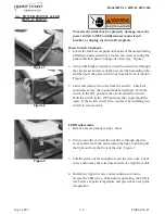
4. Install new light in reverse order, making sure not to
reverse the LED wires. When unit is operating, the LED is
red, below set- point temperature and green above set-point
temperature.
Figure 3
Содержание MPC-1L
Страница 2: ......
Страница 20: ...Model MPC 1L MPC 22 MPC 554 3 9 FM06 038 B June 2011 3 9 WIRING DIAGRAMS MPC 554...


