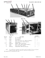
Model MPC-1L, MPC-22, MPC-554
3-2
FM06-038-B
Sept. 2007
Replacement:
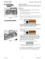
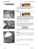
2. Disconnect the two large, white connectors and remove
component panel from unit.
3. Remove the connectors to the control board. Figure 2.
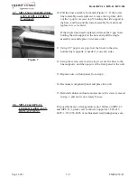
4. Using a 1/4” socket or wrench, remove the 4 nuts securing
the control board to the panel and remove control board from
panel. Figure 3.
5. Install new control board in reverse order.
Do not over-tighten the nuts securing the control board, or
the buttons on the controls may not function.
To avoid electrical shock or property damage, move the
power switch to OFF and disconnect main circuit
breaker, or unplug cord at wall receptacle.
1. Slide the component panel out as described in the first step
in Section 2-3.
Checkout:
To avoid electrical shock, make connections before
applying power, take reading, and remove power before
removing meter leads. The following checks are per-
formed with the wall circuit breaker closed and the
main power switch in the ON position.
3-3. CONTROL BOARD
(Continued)
Figure 2
Figure 3
3-4. TRANSFORMER
Содержание MPC-1L
Страница 2: ......
Страница 20: ...Model MPC 1L MPC 22 MPC 554 3 9 FM06 038 B June 2011 3 9 WIRING DIAGRAMS MPC 554...


