


Model MPC-1L, MPC-22, MPC-554
3-1
Oct. 2018
FM06-038-B
This section provides procedures for the checkout and replace-
ment of the various parts used in the cabinet. Before replacing
any parts, refer to the Troubleshooting section. It will aid you in
determining the cause of the malfunction.
1. You may want to use an ohmmeter or voltmeter to check
the electric components.
2. When the manual refers to the circuit being closed, the
ohmmeter should read zero unless otherwise noted.
3. When the manual refers to the circuit being open, the ohm
meter will read infinity.
4. When tesing the solid state relay, use the voltmeter procedure.
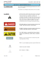
To avoid electrical shock or property damage, move the
power switch to OFF and disconnect main circuit
breaker, or unplug cord at wall receptacle.
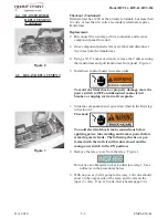
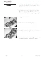
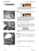
1. Locate the control access panel on the side of the unit and
using a Phillip’s-head screwdriver, or a #8 Torx socket, re
move the 2 screws securing the panel. Figure 1. Slide panel
out.
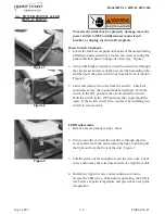
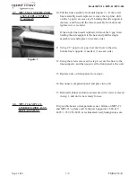
Checkout:
To avoid electrical shock, make connections before
applying power, take reading, and remove power before
removing meter leads. The following checks are per-
formed with the wall circuit breaker closed and the
main power switch in the ON position.
a. If control has no display, but recieving 12 volts at P3
connector, replace control board.
b.
If zone LED is red, but no 5 vdc shows at associated
relay, check all connections, relay polarity, and then replace
control board if necessary.
c. If zone LED is green, and 5 vdc shows at associated
relay, then replace control board
d. If any of the error codes persists, but the components are
OK, replace control board.
SECTION 3. MAINTENANCE
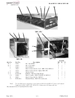
3-3. CONTROL BOARD
3-1. INTRODUCTION
3-2. MAINTENANCE HINTS
Figure 1
Содержание MPC-1L
Страница 2: ......
Страница 20: ...Model MPC 1L MPC 22 MPC 554 3 9 FM06 038 B June 2011 3 9 WIRING DIAGRAMS MPC 554...


