background image

n

Click the 

“Reset”

 button ( Fig. 38/4) to go back to previous

settings.

n

Click the 

“Clear”

 button ( Fig. 38/6) to erase all marks.

6.5  Counting

The device can use up to 10 individual bi-directional counting lines.

More than 1 line is an optional feature that requires a license for

activation.

A counting line is represented by a colored polyline with lettered

points at floor level. The line has a triangular marker which indi-

cates the direction of incoming persons, and this can be switched.

Floor Area

A

A

1

2

3

4

Fig. 41: Editing Counting Lines

n

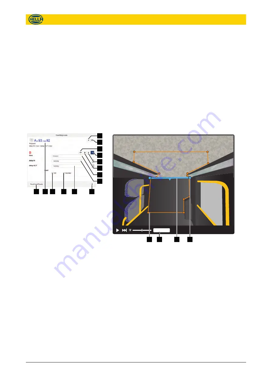
Each configured counting line is listed with it's configuration

and counting data information ( Fig. 40/13).

n

Click the 

“show/hide”

 button ( Fig. 40/2) to show or hide the

line in the live view.

n

Click the 

“Edit”

 button ( Fig. 40/1) to edit the line in the live

view.

n

Click the 

“Floor Area”

 button ( Fig. 41/3) to see the floor

( Fig. 41/4) area in the live view.

n

Define the counting line ( Fig. 41/2) by moving/adding/deleting

points ( Fig. 41/1).

Counting lines should be in the central third of the moni-

tored area so that persons can be recorded before they

cross the counting lines.

The counting lines must be at least 40 cm away from the

begin/end to the floor area in direction of movement.

Avoid gaps such that people cannot bypass the counting

lines and would not be counted.

Counting Lines

1

2

3

4

5

6

7

8

9

10

11

12

13

14

Fig. 40: Counting Lines

Configuration

Counting

09.06.2017


37

The reproduction, distribution and utilization of this document as well as the communication of its contents to others

without express authorization is prohibited. Offenders will be held liable for the payment of damages.

All rights reserved in the event of the grant of patent, utility model or design.

Содержание APS-R

Страница 1: ...Advanced People Sensor APS R and APS R PoE SW 1 2 Installation and configuration manual HAGL 120 00079 2017 06 APS R APS R PoE SW 1 2 HAGL 120 00079 2017 06 APS R APS R PoE SW 1 2...

Страница 2: ...ella com Germany Internet www people sensing com Till 07 07 2017 the company headquarters will be located at Treskowstrasse 14 13089 Berlin 2 09 06 2017 The reproduction distribution and utilization o...

Страница 3: ...ed in this manual are only deemed warran ties if they are expressly referred to as such in writing and contain a description of the warranty s scope and the product covered by the warranty The product...

Страница 4: ...3 4 6 Product labels 24 5 Installation 25 5 1 Requirements 25 5 2 Recessed mounting 26 6 Configuration 27 6 1 Preparation 27 6 2 Basic operations 29 6 3 Start Page live view 32 6 4 Camera Position 33...

Страница 5: ...n of Conformity 58 10 Glossary and abbreviations 60 11 Index 62 Table of contents 09 06 2017 5 The reproduction distribution and utilization of this document as well as the communication of its conten...

Страница 6: ...eople Sensor APS 2 Configured area monitored area 3 Counting line The results can be verified using video recording optional This enables a precise proof of the counting accuracy Overview 6 09 06 2017...

Страница 7: ...anger NOTICE This combination of symbol and signal word indicates a potentially dangerous situation which can lead to property damage data loss or misuse of the device if not avoided This symbol highl...

Страница 8: ...h must be integrated into other systems The Advanced People Sensor is exclusively intended for automati cally counting persons in the configured monitored area Proper and safe operation of the product...

Страница 9: ...ndividual persons from the video images The system integrator must establish in advance whether there are legal requirements or disclosure obliga tions at the installation site The data protection cle...

Страница 10: ...D is illuminated in red for approx imately 25 sec n After the basic system start is finished the LED goes off for approximately 15 sec n If the device is ready to use the LED is illuminated in green f...

Страница 11: ...per wires must not exceed 10 cm Jumpers DID4 No 4 DID3 No 3 DID2 No 2 DID1 No 1 Code number 0 1 2 3 4 5 6 7 8 9 10 11 12 13 14 15 DID Door IDentification Code Jumper 1 2 3 4 5 6 7 8 9 10 11 12 13 14 1...

Страница 12: ...he status LED has changed from blue to yellow the disconnect the reset pin Connect the reset pin of the I O port with pin 13 for less then 5 sec Disconnect the pin while LED illuminated in blue The de...

Страница 13: ...ood sight of the head shoulder region of all persons in the field of view The center point of the region to be monitored should be roughly in the center of the camera image Small obstacles like hand r...

Страница 14: ...ideo files and store them inter nally or automatically upload them to a remote location for later analysis The recording can be triggered via the digital inputs door contact Video recording is a very...

Страница 15: ...sible light spectrum the device is not suitable for people detection in complete darkness Examples of the illuminance provided under various condi tions Surfaces illuminated by Illuminance Candle dist...

Страница 16: ...iate result after crossing the counting line n Infinity Count only once if no U turn was made result delayed until person leaves the floor area n Time period e g 10 sec Count if the person stay longer...

Страница 17: ...0 127 6 90 4x M5 x 8 max 8 Nm 52 75 20 11 85 7 50 15 20 16 36 33 30 13 40 47 60 77 91 max 0 6 Nm UNC4 40 35 140 80 Fig 11 Dimension drawing APS R APS R PoE Technical data Mechanical data 09 06 2017 17...

Страница 18: ...t RJ45 Mode A Midspan Phantom Feed Port RJ45 Mode B Endspan Spare wire feed Pin allocation 1 2 3 4 5 Fig 12 M12 Ethernet interface Technical data Hardware interface specifications Ethernet 18 09 06 20...

Страница 19: ...ntial free 10 IN0 Programmable input potential free 11 IN1 Programmable input potential free 12 DID4 B Code jumper 4 13 DID3 B Code jumper 3 14 DID2 B Code jumper 2 15 DID1 B Code jumper 1 Pin Allocat...

Страница 20: ...ammable input potential free 11 DID4 B Code jumper 4 12 DID3 B Code jumper 3 13 DID2 B Code jumper 2 14 DID1 B Code jumper 1 15 PWR DC Power supply input Pin Allocation APS R 1 2 3 4 5 6 7 8 9 10 11 1...

Страница 21: ...out power interruptions With regard to the use in trains the APS R PoE will withstand short power interruptions of approx 5 ms which is close to EN 50155 class S2 This behavior deviates from the PoE s...

Страница 22: ...ng the ground stud Category Description Transfer rate 10 100 Mbit s Cable length maximum 100 m Connector type M12 D coded 4 pin female 4 4 Optical data Category Description Image resolution 640 x 480...

Страница 23: ...rs Fire safety DIN EN 45545 2 2015 A1 2015 grouping rule 1 applies less than 100 g com bustible mass ISO 3795 UL94 UL94 Class V0 Shock and vibration EN 50125 1 IEC 61373 cat 1 class B applied test met...

Страница 24: ...trix code serves a serial number and con tains the following information in encoded form n MAC address n Production date n Production place n Version revision Identification Label 1 2 3 4 5 6 7 8 9 10...

Страница 25: ...d area should be through the center The counting line Fig 17 3 should be in the central third of the monitored area Fig 17 2 so that persons can be recorded before they cross the counting line The beg...

Страница 26: ...s to fix the holder 9 Use the ground stud Fig 20 3 to ground the device 10 Connect the grounding cable to the equipotential bonding ter minal 11 Connect the network cable Fig 20 2 12 Plug in the confi...

Страница 27: ...E Fig 21 3 n PC or tablet with DHCP Fig 21 4 n Ethernet cable Fig 21 10 to con nect Device with switch injector n Ethernet cable Fig 21 5 to con nect switch injector with PC tablet Connecting directly...

Страница 28: ...LED red on starting up for approx 25 sec off for approx 15 sec LED green for approx 3 sec and then off 3 Access your router or DHCP Software to find the IP address used by the device Search for the u...

Страница 29: ...he unsaved settings from the current view The design of the user interface is responsive The appearance of the user interface depends on the used configuration device All user interface figures shown...

Страница 30: ...er selecting a menu category the related configuration page opens In each menu category several topics are summarized as topic blocks These topic blocks will automatically reposition and resize based...

Страница 31: ...bar Select an icon to go to a certain configuration category Select the Home icon to go to the Start Page see Fig 24 1 2 3 4 Fig 28 Navigation bar 1 Collapse icon 2 Expanded view 3 Collapsed view 4 Ex...

Страница 32: ...iting is possible in the corresponding overlay view showing in the camera view 2 Click and hold a polygon point to move it 3 Double click a polygon point to remove it 4 Double click a polygon line to...

Страница 33: ...unting lines can be shown 1 Show hide the counting line in the live view 2 Count for incoming and outgoing persons 3 Sets the count information to 0 in the user interface Reset has no effect on intern...

Страница 34: ...t is the distance between the device level and the floor level The floor area is the range where people be tracked and counted Static objects like walls or seats has to be left out the floor area Obst...

Страница 35: ...e floor area by moving adding deleting points Fig 35 5 The floor area is defined by a minimum of 3 points and a maximum of 20 points Range Floor Area Obstructions 1 2 Fig 37 Live View with stairs in t...

Страница 36: ...bjects in the live view Obstructions Range Floor Area Obstructions Range Floor Area 1 2 3 Fig 39 Live view with partial marked obstructed object n Click the Obstructions button Fig 39 1 to see marked...

Страница 37: ...40 1 to edit the line in the live view n Click the Floor Area button Fig 41 3 to see the floor Fig 41 4 area in the live view n Define the counting line Fig 41 2 by moving adding deleting points Fig...

Страница 38: ...o save all the settings in the device n Click the Reset button Fig 40 5 to go back to previous settings n Click the Delete button Fig 40 6 to remove the counting line n Click the Plus button Fig 40 9...

Страница 39: ...r automatic upload of completed files File upload must be activated and defined in File Upload Settings on page 40 n Click the Save button Fig 42 16 to save all the settings in the device n Click the...

Страница 40: ...the Save button Fig 43 5 to save all the settings in the device n Click the Reset button Fig 43 2 to go back to previous settings n Click Download Data Files Fig 43 3 for immediate down load of all d...

Страница 41: ...n Click the Save button Fig 46 7 to save all the settings in the device n Click the Reset button Fig 46 6 to go back to previous settings Domain Name System servers translate FQDN fully qualified doma...

Страница 42: ...secured HTTPS connection Fig 49 2 n Set the Push Service server address Fig 49 3 and port n Enter SOAP Service Name as path to the server URL Fig 49 4 n Check Use Proxy for Push Services Fig 49 5 if...

Страница 43: ...Settings Use the Other Settings page to set date and time manually to change the login passwords or set update information Date and time is used for time stamps in data recording and proto cols The d...

Страница 44: ...pdate server This URL is used for firmware and parameter updates n When using a configured and working DHCP server tick the Obtain Update Server IP via DHCP option 72 checkbox Fig 55 7 to receive the...

Страница 45: ...opens up the user interface automatically to enable further configuration Parameters sets that were exported from older firmware releases will be automatically updated during the import n For Hella Ag...

Страница 46: ...erate a new image from the actual view n The privacy image is optional used in some diagnosis 6 10 About The About category gives system information Combined with Diagnosis Data this can be very usefu...

Страница 47: ...tal number of system resets n Number of system power ups n Number of hardware watchdog events n Number of software watchdog events n Number of unknown reset events n Current CPU Temperature C this is...

Страница 48: ...the size content and transparency for the Top Marker Fig 69 5 or the Ground Marker Fig 69 8 n Choose the thickness Fig 69 6 and transparency Fig 69 7 for the Center line n Choose the Display Position...

Страница 49: ...ring n Check Ethernet cabling n Check status LED of Ethernet switch n Check status LED of the device after connecting with power LED red on starting up for approx 25 sec off for approx 15 sec LED gree...

Страница 50: ...masked correctly in floor area n If obstructions are masked correctly If checks are negative reconfigure the device Modified mounting position Check in the user interface n If the adjusted pitch and...

Страница 51: ...dress HELLA AGLAIA Mobile Vision GmbH Ullsteinstrasse 140 12109 Berlin Germany Till 07 07 2017 the company headquarters will be located at Treskowstrasse 14 13089 Berlin Please clearly mark the goods...

Страница 52: ...10 50 15 65 13 12 340 524 440 133 9 206 3 173 2 11 15 17 19 14 43 360 572 480 141 7 225 2 189 0 11 81 18 76 15 74 380 620 520 149 6 244 1 204 7 12 46 20 34 17 06 400 667 560 157 5 262 6 220 5 13 12 2...

Страница 53: ...setup user Home Camera view Live view with counting line and tracking objects Device Information Status of the visible range and the configura tion of the programmable inputs Counts Counting Informati...

Страница 54: ...ools Common Tasks Reboot and locate the device Firmware Update Update the device Firmware Parameter Export Export of all parameters to a file on the PC Parameter Import Import of all parameters from a...

Страница 55: ...Menu Structure 09 06 2017 55 The reproduction distribution and utilization of this document as well as the communication of its contents to others without express authorization is prohibited Offenders...

Страница 56: ...L APS 80 configurable TCP Push data to server via http Push Services SOAP XML APS 443 configurable TCP Secure push data to server via https IBIS IBIS protocol over Ethernet VDV300 APS 10076 UDP Extern...

Страница 57: ...blic License Copyright C 1989 1991 Free Software Foundation Inc Busy Box GNU General Public License Copyright C 1989 1991 Free Software Foundation Inc FFMPEG GNU General Public License Copyright C 198...

Страница 58: ...6 2017 The reproduction distribution and utilization of this document as well as the communication of its contents to others without express authorization is prohibited Offenders will be held liable f...

Страница 59: ...roduction distribution and utilization of this document as well as the communication of its contents to others without express authorization is prohibited Offenders will be held liable for the payment...

Страница 60: ...the web browser HMI of the APS HTTP Hypertext Transfer Protocol Application protocol for data transmissions in networks HTTP is the basis for data communications in the World Wide Web HTTPS Hypertext...

Страница 61: ...inated Universal Time UTC is the main time standard by which the world regulates clocks and time VPN Virtual Private Network Technology using the Internet to connect computers to iso lated remote comp...

Страница 62: ...2 Reset 12 IBIS 42 IBIS IP 43 Identification label 24 Illumination 15 Import Licence file 45 parameter 45 Ingress Protection 23 Inrush current 21 22 Installation heights 13 Installation kit 26 Intende...

Страница 63: ...th status 47 System integrator 7 T Target group 7 Telnet 43 Time 43 Time Zone 43 Topic blocks 30 Track object 48 Trigger 12 Troubleshooting 49 U U turn 16 Update Firmware 44 45 Parameter 44 Update aut...

Страница 64: ......

Страница 65: ...2017 HELLA AGLAIA Berlin HAGL 120 00079 2016 11 APS R APS R PoE SW 1 2 HELLA AGLAIA Mobile Vision GmbH Ein Unternehmen der HELLA Gruppe Ullsteinstrasse 140 12109 Berlin...

Отзывы: