CCR961 MANUAL-GB
21
Version B2:01-07-2015
5
Commissioning
5.1
Preparation
Commissioning and adjustment normally have to be certified in a protocol. This protocol can be
made by means of the serial interface on front of the CCR together with a Monitor Program, or it
can be done by hand on, by reading values in the display.
A.
Conditions for a correct adjustment:
The CCR is wired for correct supply voltage (230V or 400V, factory setting is 400V)
Remote control address is set to correct value
The series circuit is controlled for acceptable isolation value and continuity
The remote control cable is connected
B.
Assembling:
The Key switch is set in position ”OFF” (= AUS).
Power is switched on
No blinking must occur in the display
The Key - switch is turned to position ”Manual” (local operation)
C.
Setting and adjustments:
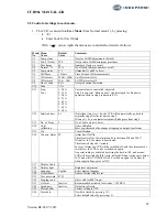
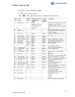
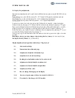
There are more menu areas:
Normal menu (no access code needed) with the menu’s N1 – N12
User menu (user code) with the menu’s U1 – U 21
Factory menu (factory code) with the menu’s F1 – F19
Normal menu is only for display of data, User and Factory menu are for setting and adjustment of
the CCR.
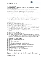
The following adjustment procedure is valid for CCR’s supplied directly from work, where
Default data are activated and the CCR is calibrated for Iout.
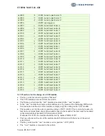
The CCR will work without additional settings, but for full function of lamp supervision etc., the
following control / adjustments in the relevant menu can be performed.
The User- and Factory menus can only be accessed by the use of a code. The codes will be listed
in the enclosed Factory Test protocol.
Содержание CCR 961-SW4.00
Страница 1: ...Regulator type CCR 961 SW4 00 USER MANUAL GB...
Страница 9: ...CCR961 MANUAL GB 9 Version B2 01 07 2015...
Страница 13: ...CCR961 MANUAL GB 13 Version B2 01 07 2015...
Страница 19: ...CCR961 MANUAL GB 19 Version B2 01 07 2015 CCR front view...
Страница 36: ...CCR961 MANUAL GB 36 Version B2 01 07 2015...


