CCR961 MANUAL-GB
12
Version B2:01-07-2015
Trigger Module
This module converts the control signal from the
-processor to galvanic separated power
signals to the thyristors.
To be able to guarantee triggering (activation) of the thyristors under difficult
circumstances (such as reactor load) the trigger signal is not only a single pulse, but a large
number of trigger pulses.
The Trigger module does also include a galvanic separation (Solid State Relay) between
the on signals from the Main Board to the main contactor.
In the same manner the cyclic control of the ISO measurements are performed. When a
measurement is requested, 42VAC is connected to the ISO box via a Solid State Relay.
Remote Control System
The Main Board Module includes a standard RS485 communications port. This can be
connected directly to the remote control system.
For more sophisticated protocols, an additional printed board can be built into the CCR
module. As standard, Hella Induperm can offer Profibus or redundant Profibus plug-in
boards.
If IP addresses are requested, an IP module is placed in the CCR cubicle and
communicates with the module though our RS485 serial communication.
If parallel interface to a remote control system is requested, a Parallel interface module is
placed in the CCR cubicle and communicates with the module though the RS485 serial
communication.
Information Display
The CCR Module is equipped with a large LCD display.
The following information can be seen in the display:
Output Current
Output voltage
Output power
Time and date
Hour meters
Selected step
Actual regulation reserve
Alarms
Number of faulty lamps
Isolation level
From the front of the CCR Module, it is possible to change all settings.
As mentioned, the CCR module is a plug-in unit.
The electrical connections:
Power input (N+PH or PH+PH, +Ground)
Power output to power transformer (output transformer)
Current feed-back measurement
ISO measuring
Serial communication (RS485 or Profibus)
are all done via our special high performance connector. The connector is mounted on screws with
springs, which will secure full contact in the connector. That’s the reason, why it is important that
the module after plug-in is fastened with the screws in the front.
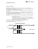
The wiring of the module and connections to Output transformer and measuring signals, is shown
on the diagram on the following page.
Содержание CCR 961-SW4.00
Страница 1: ...Regulator type CCR 961 SW4 00 USER MANUAL GB...
Страница 9: ...CCR961 MANUAL GB 9 Version B2 01 07 2015...
Страница 13: ...CCR961 MANUAL GB 13 Version B2 01 07 2015...
Страница 19: ...CCR961 MANUAL GB 19 Version B2 01 07 2015 CCR front view...
Страница 36: ...CCR961 MANUAL GB 36 Version B2 01 07 2015...


