background image

- 29 -

Service Call 0844 736 9138, Technical Help (Chargeable) Call 0906 802 0253

15.1.2 

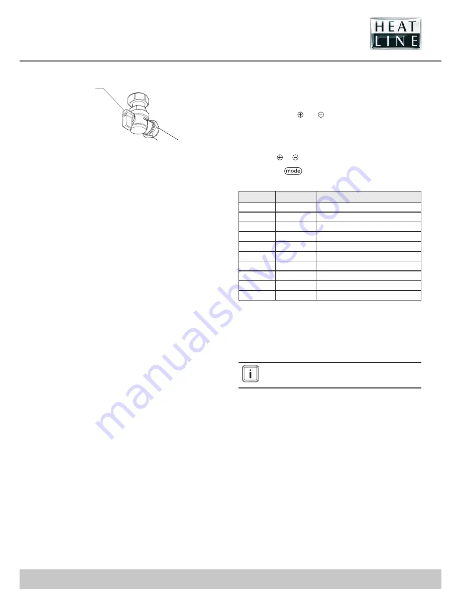
Check the gas supply

1

YELLOW

Key

1  Gas service isolation valve

•  Check that there is a gas supply to the boiler and the gas 

service isolation valve is turned on. 

•  Check pressure at the gas service isolation valve.

15.2  Fault memory

•  This menu allows you to display the 10 most recent failure 

codes registered by the appliance.

•  In order to display the fault code memory, simultaneously 

press the buttons


and


for more than 7 seconds.

•  The screen will display the fi rst fault "1." (record) and after 

"XX" (fault code).

•  To display the other faults registered by the appliance, press 

the button


or

   .

•  Press button


for more than 3 seconds to exit this 

menu.

Record

Fault code

Description

1.

XX

Consult the “Fault codes” chapter.

2.

XX

Consult the “Fault codes” chapter.

3.

XX

Consult the “Fault codes” chapter.

4.

XX

Consult the “Fault codes” chapter.

5.

XX

Consult the “Fault codes” chapter.

6.

XX

Consult the “Fault codes” chapter.

7.

XX

Consult the “Fault codes” chapter.

8.

XX

Consult the “Fault codes” chapter.

9.

XX

Consult the “Fault codes” chapter.

10

XX

Consult the “Fault codes” chapter.

•  To erase the fault memory registered by the appliance, 

consult the “Installation adjustments” chapter and use code 

“d.94”.

15.3  Fault codes

The faults described in this chapter should be carried 

out by a qualifi ed engineer and if needed by the After 

Sales Service.

Содержание CaprizPlus 24

Страница 1: ...Combination Boilers www heatline co uk Models 24 G C No 47 157 19 28 G C No 47 157 20 CaprizPlus Service Call 0844 736 9138 Technical Help Chargeable Call 0906 802 0253 bar 1 2 3 4 0 22 21 20 19 18 17 16 15 14 13 12 11 10 9 8 7 6 5 4 3 2 1 24 23 mode reset ...

Страница 2: ...cheme Visit www central heating co uk for more information Thank you for installing a new Heatline appliance in your home Heatline appliances are manufactured to the very highest standard so we are pleased to offer our customers a Comprehensive Guarantee For the manufacturer s warranty to be valid the Benchmark Log Book must be correctly completed by a suitably qualified person and be available fo...

Страница 3: ...ion 2 1 Safety devices Overheating Safety Device The appliance is designed to recognise the potential of an overheat situation and will shutdown before a potentially dangerous situation occurs Safety discharge valve A safety discharge valve and discharge pipe are fitted to the boiler This valve must not be touched The heating safety valve opens when the pressure in the heating circuit exceeds 3bar...

Страница 4: ...s of Statutory Instrument No 3083 The Boiler Efficiency Regulations and therefore is deemed to meet the requirements of Directive 92 42 EEC on the efficiency requirements for new hot water boilers fired with liquid or gaseous fuels Type test for purposes of Regulation 5 certified by Notified body IMQ 52BP2727 CE Directives 2009 142 EEC 52BP2728DR CE Directives 92 42 EEC Product production certifie...

Страница 5: ...handling and cleaning with particular regard to edges The basic safety instructions must be followed before attempting to maintain or replace spare parts Electrically isolate the appliance from the power supply Turn off the appliance gas isolation valve Hydraulically isolate the appliance using the isolation valves below the boiler Protect all the electrical components from water while working on ...

Страница 6: ...d type and all wiring to current I E E wiring regulations External wiring must be correctly earthed polarised and in accordance with the relevant standards In GB this is BS 7671 In IE this is the current edition of ETCI rules The boiler MUST be connected to a permanent 230V ac 50Hz supply Connection of the whole electrical system of the boiler including any heating controls to the electrical suppl...

Страница 7: ... min 9 4 11 4 Minimum inlet water pressure bar 0 8 0 8 psi 11 6 11 6 Maximum inlet water pressure bar 10 0 10 0 psi 145 145 Combustion Appliance NOX Class 5 5 Description Unit 24 28 Electrical Electrical supply V Hz 230V 50Hz 230V 50Hz Standby mode electrical power W 3 3 Operating mode electrical power W 130 130 Internal fuse rating on main PCB A 2 2 Index of electrical protection EN 60529 IPX4D I...

Страница 8: ...e should be made to the current edition of I S 813 Domestic Gas Installations and the current ETCI rules Timber Frame Buildings If the boiler is to be installed in a timber frame building it should be fitted in accordance with the Institute of Gas Engineers document IGE UP 7 1998 If in doubt seek advice from local gas undertaking or Heatline 6 2 Clearances The clearances specified are the minimum ...

Страница 9: ... the supply to the boiler Hard water areas The temperatures within the heat exchanger are limited by the boiler control system to minimise scale formation within the hot water pipework However in areas where the water is hard i e more than 200 mg L of calcium carbonate it is recommended that the hot water setting is reduced and that a scale reducer is fitted refer to the manufacturer s instruction...

Страница 10: ...grammatically see diagram Heating circuit design The system should be pressurised to 1 0bar indicated on the digital display with no heating demand Drain points Drain taps must be provided at all low points of the system which will allow the entire system to be drained Drain taps shall be to the current issue of BS2879 Water treatment Existing system It is essential that prior to installing the ne...

Страница 11: ...60 100 flue If flue extension pipes are to be used then a core drill size of 125mm is required This will allow the extension pieces to slope at 44mm metre 2 5o towards the boiler If fitting a side flue extend the flue centre line into the corner then 130mm along the adjacent wall If fitting an extended side flue determine the flue hole centre by extending the dashed inclined line on the template to...

Страница 12: ...ance and interrupt its operation Ensure that the appliance is disconnected before cleansing the system Do not use any solvent products due to the risk of damaging the circuit a Do not perform any hot work directly under the appliance this may cause damage to the appliance base Heat may also damage the isolation valves Always pre assemble pipes before fitting them to the boiler Only use original sea...

Страница 13: ... 13 Service Call 0844 736 9138 Technical Help Chargeable Call 0906 802 0253 ...

Страница 14: ...strongly advised that condensate is discharged into the household internal drainage system Note some installations may require the use of a condensate pump in order to achieve internal discharge If internal discharge is not practicable discharge can be allowed into the external household drains or a purpose built soak away refer to diagram overleaf and BS5546 or BS6798 for reference and advice How...

Страница 15: ...icated in the chart below to position the flue terminals To install the flue refer to the flue instructions Explain these requirements to the user of the appliance a If necessary you must install a flue terminal guard Caution The connection between the flue elbow and the flue outlet must be sealed In GB the minimum acceptable siting dimensions for the terminal from obstructions other terminals and ve...

Страница 16: ...alongside the terminal 300 I above adjacent ground or balcony level 300 Position Position of the flue terminal mm J 2 from surface or a boundary facing the terminal 600 L from opening door window in car port into dwelling 1200 M vertical from a terminal 1500 N horizontally from a terminal 300 Vertical flues P from another terminal 600 Q above roof level 300 R from adjacent opening window 1000 S fr...

Страница 17: ...ont panel and controls fascia 2 1 Key 1 Controls fascia 2 Controls fascia retaining screw Release the controls fascia 1 by loosening the securing screws 2 NOTE Do not remove the screws as they are held in place by a circlip 1 2 2 3 Key 1 Front panel 2 Front panel retaining screw 3 Pressure guage capillary grommet Undo the two screws 2 on the underside of the front panel and remove the front panel ...

Страница 18: ... a connector on the electronic board Keep a distance of a maximum of 30 mm between connector 1 and the start of the insulation 3 If using single core wires are used 2 ensure that the are wrapped together in an insulating sheath Fix the cables in the cable clamp on the eBox 10 4 Electrical wiring Connection of the whole electrical system and any heating system controls to the electrical supply must...

Страница 19: ...thout a link or system controls fitted The frost thermostat will only operate the boiler when in Winter mode DHW CH If 230V thermostats are connected into RT then they must all be fed from the same live source as the boiler If any external 24V or 230V thermostats are connected this link should be removed 10 5 External accessories e Under no circumstances must any mains voltage be applied to any of ...

Страница 20: ...rvice Call 0844 736 9138 Technical Help Chargeable Call 0906 802 0253 10 7 Wiring diagram DESCRIPTION B BLACK BR BROWN R RED Y G YELLOW GREEN BL BLUE G GREEN GY GREY W WHITE P PINK O ORANGE PP PURPLE Y YELLOW ...

Страница 21: ...bed b Vent all air from the system repeat as necessary until the system is full and all the air has beren removed c To comply with the water regulations the filling loop connection must be removed 1 3 2 Key 1 Air vent 2 Pump 3 Screw for the pump shaft Open the plug on the air vent located on the pump and automatic air vents on the installation If the CH pressure falls below 0 4 bar the display wil...

Страница 22: ... ON OFF and Mode selection button 3 Display 4 Temperature adjustment 5 Anologue clock 6 Reset button Display Light the appliance by following the procedure below Select the Heating domestic hot water function by pressing the Mode button repeatedly to scroll through your options until are shown The appliance will enter a self checking routine then the fan will start and the ignition sequence commen...

Страница 23: ...t the external controls and programmer are calling for heat Fully open all radiator valves see chapter Appliance installation Recommendations before installing Heating circuit design Activate the C H function on the appliance s control panel Balance the radiators as required to give the required system differential Turn off all radiators that can be shut off by the user and check to see if less th...

Страница 24: ...s middle position HEATING 35W V2 bypass opened HEATING 35W V1 bypass closed HEATING 35W V2 bypass closed HEATING 35W V2 bypass middle position HEATING 35W V2 bypass opened KEY KEY CaprizPlus 24 25kW 0 0 1 0 2 0 3 0 4 0 5 0 6 0 0 100 200 300 400 500 600 700 800 900 1000 1100 1200 1300 1400 1500 0 100 200 300 400 500 600 700 800 900 1000 1100 1200 1300 1400 1500 Water Flow in L hr Available pressure...

Страница 25: ...of fan rpm 100 Domestic Hot Water 0 Central Heating no d 35 3 way valve position step Fan speed is displayed between 0 and 99 Multiply the display value by 100 d 36 Domestic hot water flow l min Display domestic hot water flow no d 40 Heating flow temperature C Display the heating flow temperature no d 41 Heating return temperature C Display the heating return temperature no d 67 Time remaining be...

Страница 26: ...of the appliance Press button for 7 seconds to learn the current state of functioning of the appliance The screen displays S and the state of the appliance To exit to display menu press the button for 3 seconds Status Heating Mode S 00 No request for heating S 01 Pre run fan S 02 Pre run pump S 03 Ignition S 04 Burner lit S 05 Post run pump fan S 06 Post run fan S 07 Post run pump S 08 Time delay ...

Страница 27: ...is appliance has been pre set at the factory for operation on Natural Gas G20 as defined on the appliance data label No adjustment of the combustion is necessary If you wish to check the combustion then follow the instructions in the Servicing section 13 2 Re check and restart Once the appliance is installed check the operation of the appliance Start the appliance to ensure that any adjustments op...

Страница 28: ...ist located in the back pages of this document 15 Trouble shooting 15 1 Fault diagnosis The following checks should be performed before proceeding onto specific diagnostics Make sure that the electricity supply has not been interrupted and that the appliance is connected correctly See chapter Trouble shooting Fault diagnosis Check the electrical installation Check the appliance s gas supply See ch...

Страница 29: ...display the other faults registered by the appliance press the button or Press button for more than 3 seconds to exit this menu Record Fault code Description 1 XX Consult the Fault codes chapter 2 XX Consult the Fault codes chapter 3 XX Consult the Fault codes chapter 4 XX Consult the Fault codes chapter 5 XX Consult the Fault codes chapter 6 XX Consult the Fault codes chapter 7 XX Consult the Fau...

Страница 30: ... Defective igniter unit Check the return gas circuit gas valve open Check the observe the flame picture and check the CO2 setting Check the igniter unit connections Check the state of the electrode corrosion F29 Loss of flame during operation F32 Incorrect air pressure Incorrect fan speed Check the entire flue system Check the fan s electrical connections F49 EBUS voltage fault Fault in EBUS line ...

Страница 31: ...p disconnected Leak in the installation Fill the installation Purge the installation Check the pump connections Check the flow and return heating sensor connections Check that there are no leaks F84 Permanent temperature difference between flow and return heating sensors Inverted or disconnected flow and return heating temperature sensors Defective temperature sensors Check temperature sensors con...

Страница 32: ...run on LPG requires a conversion kit The kit and the conversion operation must be done by the Heatline Service Team please ring 0844 736 9138 Please note that if the appliance requires conversion the installer should be qualified by Gas Safe Register to install LPG appliances in order to complete the installation and its notification after conversion has been done ...

Страница 33: ...n circuit and the relevant seals The operational working gas inlet pressure at maximum rate The gas rate The combustion performance See the Safety instructions chapter for a list of operations to be performed prior to the maintenance of the application Once the maintenance operations have been completed consult the Start Up chapter to restart the appliance 18 1 Annual Maintenance 18 1 1 Verificati...

Страница 34: ... Specification for installation and maintenance of gas fired boilers of rated input not exceeding 70kW net advises that The person carrying out a combustion measurement must be assessed as competent in the use of a flue gas analyser and the interpretation of the results The flue gas analyser used should be one meeting the requirements of BS7927 or BS EN50379 3 and be calibrated in accordance with th...

Страница 35: ...e test modes Remove the analyser probe and replace the cap on the sampling point replace the controls fascia and the front casing panel Remember to replace the sample point cap on completion of the test 18 2 4 Gas rate check Check the gas rates as described in the commissioning section 18 2 5 Completion If it is not possible to achieve the required results for either the combustion or gas rates it...

Страница 36: ... from blockage After draining the boiler as previously described push and turn the filter cap in an anti clockwise direction to release it from its housing Pull the cap out with the filter attached Clean and replace as necessary refilling and re pressurising the boiler as required 18 7 Heating filter 1 2 BLUE 3 Key 1 Filter 2 Filter valve body 3 Cap The filter valve located under the boiler at the...

Страница 37: ...ner under the condensate trap 5 Disconnect the condensate pipe from the reservoir 1 Disconnect the condensation reservoir 2 Disconnect the condensate drain 3 and the rain water collector 4 from the heat exchanger The condense trap will contain water lift taking care not to spill the water Remove the screws 6 to disconnect the condensate trap 5 Clean the hose the trap and the siphon remove any accu...

Страница 38: ... 7 8 9 Legend 1 Gas valve connection 2 Grounding cable 3 Spark electrode inlet 4 Spark electrode retaining screw 5 Spark electrode gasket 6 Spark electrode 7 Burner retaining nut 8 Burner retaining screw 9 Thermal fuse connection 10 Coil 11 Heat exchanger 12 Burner door seal 13 Burner 14 Gas valve 15 Fan 16 Fan connection 17 Gas pipe ...

Страница 39: ...9 in the heat exchanger 11 with water 18 9 4 Burner control The burner 13 does not require maintenance and should not be cleaned Check that its surface is not damage Replace the burner if necessary Following the verification or replacement of the burner assemble the burner group as described in the following chapter 18 9 5 Re assembling the burner group Place the burner group on the heat exchanger...

Страница 40: ... test of the controls 19 2 Boiler Access For replacement of parts the front casing panel of the boiler will need to be removed To remove undo the two screws on the underside of the front casing and open the control box door Remove the two front panel retaining screws which are now accessible and remove the front panel 19 3 Viewing window 3 4 5 2 1 Key 1 Fibre washer 2 Steel washer 3 Glass 4 Steel ...

Страница 41: ...ilter assembly 10 Heating flow pipe retaining clip 11 Gas pipe 12 Flow sensor electrical plug 13 Flow sensor 14 Heating return pipe 15 Expansion vessel pipe 16 Plate to plate heat exchanger 17 Automatic air vent 18 Expansion vessel pipe clip 19 Automatic air vent retaining clip 20 Pump head retaining screws 21 Pump housing 22 Pump head connector 23 Plate to plate heat exchanger retaining screws 24...

Страница 42: ...d remove the pipe Disconnect the Central Heating isolation valve Remove the securing clips and withdraw the safety discharge valve plastic housing 29 Remove the safety discharge valve Fit new O ring Refill vent and pressurise the boiler 19 4 5 Flow sensor and impeller Remove the the electrical connection 12 Unclip the flow sensor 13 Unscrew the impeller housing 28 and remove the impeller 19 4 6 By...

Страница 43: ...ion burner door assembly nut 13 Combustion burner door assembly gasket 14 Burner gasket 15 Burner 16 Burner retaining screw 17 Heat exchanger retaining screw 18 Heat exchanger retaining bracket 19 Burner gate retaining screw 20 Thermal fuse connection 21 Heat exchanger 22 Heat exchanger retaining bracket 23 Heat exchanger retaining screw 24 Heating return pipe 25 Heating return pipe retaining clip...

Страница 44: ...5 Heat exchanger There will be water in the heat exchanger Carefully ease heat exchanger out Drain the boiler heating and hot water circuits as described in the appropriate chapter Draining Remove the flue connection Undo the two screws located on the top of each side panel Remove the thermal fuse connector 20 Remove the 2 heating pipe retaining clips 25 and 29 Release the heating pipes 24 and 27 ...

Страница 45: ...as valve 31 see previous paragraph Loosen the 3 screws 38 located on the burner door 11 Remove the fan 33 and the gasket 35 Fit the new gasket 35 Screw the new fan to the burner door 11 After assembly test for gas tightness and purge in accordance with the current issue of BS6891or in IE the current edition of I S 813 Domestic Gas Installations 19 6 Condensate trap a Warning condensate is mildly a...

Страница 46: ...19 7 2 2A Fuse Rating For access refer to chapter Main PCB The fuse is located at top right hand side of the PCB see chapter Electrical connection Wiring diagram 19 7 3 User interface PCB 3 1 2 Key 1 Retaining clips 2 User interface PCB 3 Electrical connection Ease back the PCB retaining clips 1 and withdraw the user interface PCB 2 from the retaining lugs Remove the electrical connection 3 to the...

Страница 47: ...dering spare parts contact Heatline s own service organisation Please quote the name of the appliance and serial number to be found on the data label Key No Part No Description GC Part No 1 0020117666 Fan 2 0020111021 Spark igniter 3 0020126681 Thermistor flow and return 4 0020116832 Gas valve 24 0020097278 Gas valve 28 5 0020038441 Electrode assembly 6 D003202903 User interface PCB 7 D020116522 P...

Страница 48: ... polystyrene end packs Remove top polystyrene pack with fittings Positioning of Appliance for Final Installation no obstructions Recommend 2 persons lift appliance to position into place Fit bracket securely onto wall before lifting appliance into position Obtain firm grip on front and sides of appliance lift upwards ensure stable bal ance achieved and lift upwards to position in place on bracket ...

Страница 49: ......

Страница 50: ...ffect the customer s statutory rights If yes and if required by the manufacturer has a water scale reducer been fitted CONDENSING BOILERS ONLY The condensate drain has been installed in accordance with the manufacturer s instructions and or BS5546 BS6798 Yes If the condensate pipe terminates externally has the pipe diameter been increased and weatherproof insulation fitted Yes ...

Страница 51: ...eer Name Company Name Telephone No Gas Safe Register No Comments Signature Date Engineer Name Company Name Telephone No Gas Safe Register No Comments Signature Date Engineer Name Company Name Telephone No Gas Safe Register No Comments Signature Date Engineer Name Company Name Telephone No Operative ID No Comments Signature Date Engineer Name Company Name Telephone No Gas Safe Register No Comments ...

Страница 52: ...www heatline co uk Service Call 0844 736 9138 Technical Help Chargeable Call 0906 802 0253 Heatline Nottingham Road Belper DE56 1JT 0020112883 03 06 11 ...

Отзывы: