Page 22
Operations Manual SC-610
Harmonic Drive AG
900105
11/2005
4.2 Control- and Signal Wiring
This chapter is valid for all versions.
The wiring of the control in- and outputs can be achieved with
one
cable only unlike shown in the pictures
below. The outputs
can be
wired. But there is no need for drive operation.
4.2.1 Control Inputs
The control inputs below are opto-isolated. The ground return for all inputs is "CREF", connector X3.7.
Please note there are two different pin assignments for connector X3 available.
The drive can configured either in current, pulse follower, handwheel or velocity mode.
The drive is also equipped with a third control loop. Here it is a point-to-point positioning feature
implemented. Up to 16 different positions (optional 256) can be stored inside the drive. These positions
(including the homing routine) can be selected with the digital inputs and executed with the trigger input.
Positioning is possible with actuators providing Hiperface and resolver feedback. Actuators equipped with a
multiturn absolute Hiperface encoder (SCM-101) do not need a homing cycle since the absolute position is
determined after power on of the drive.
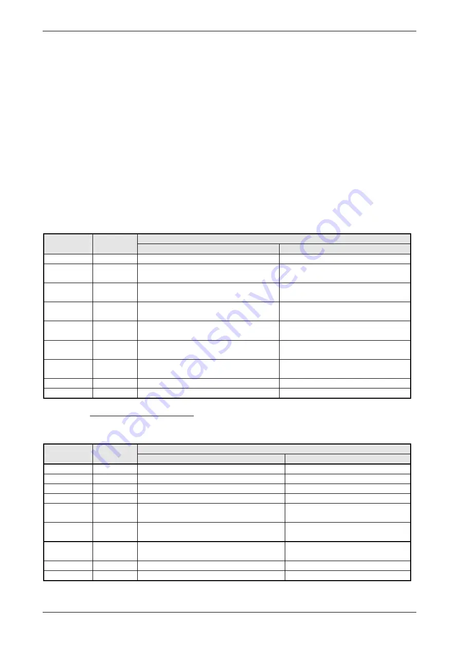
Control Input Function:
Example Configuration for Speed Control and Pulse Follower
Signal
Connector
Switch Position / Function
Pin
closed
open
ENABLE
X3.9
Drive enabled
Drive disabled
DIN 0,
CWLimit
1)
X3.10
Clockwise direction of rotation enabled
Clockwise direction of rotation
disabled
DIN 1,
CCWLimit
1)
X3.11
Counter clockwise direction of rotation
enabled (or position selection)
Counterclockwise dir. of rotation
disabled
DIN 2,
STOP
X3.12
STOP Function is active
STOP function is not active
DIN 3
FRESET
X3.13
RESET function is active
Rising edge
RESET function is not active
DIN 4,
Pulse
X3.14
Input pulse train (see below)
DIN 5,
Direction
X3.15
Direction signal (see below)
DIN 6
X3.16
Digital input 1 = logical 1
Digital input 1 = logical 0
DIN 7
X3.17
Digital input 2 = logical 1
Digital input 2 = logical 0
1)
Please note that servo axes incorporating Harmonic Drive gears (i. e. FHA-, FFA- and RS-series) will be
effected by a change of the turning direction. The
MOTORDIRECTION
keyword can be used to change motor
direction.
Example Configuration for Position Control
Signal
Connector
Switch Position / Function
Pin
closed
open
ENABLE
X3.9
Drive enabled
Drive disabled
DIN 0
X3.10
Input no. 2 for position selection
DIN 1
X3.11
Input no. 3 for position selection
DIN 2,QUIT
X3.12
Quit running positioning process
Positioning process will be done
DIN 3,
FRESET
X3.13
RESET function active
RESET function not active
DIN 4,
HOME FLAG
X3.14
Home flag =
closing (or rising) edge
Home flag =
opening (or falling) edge
DIN 5,
TRIGGER
X3.15 Trigger
=
closing (or rising) edge
Trigger =
opening (or falling) edge
DIN 6
X3.16
Input no. 0 for position selection
DIN 7
X3.17
Input no. 1 for position selection
Wiring proposal for control inputs see chapter 4.3. Hardware description of the inputs refer to chapter 7.
Содержание SC-610 Series
Страница 1: ...Operations Manual AC Servo Controller SC 610 No 900105 11 2005 24 11 2005 FA...
Страница 3: ......
Страница 52: ...Operations Manual SC 610 Page A1 Harmonic Drive AG 900105 11 2005 APPENDIX...
Страница 64: ...Operations Manual SC 610 Page A13 Harmonic Drive AG 900105 11 2005 APPENDIX G...
Страница 65: ...Page A14 Operations Manual SC 610 Harmonic Drive AG 900105 11 2005 APPENDIX H...
Страница 66: ...Operations Manual SC 610 Page A15 Harmonic Drive AG 900105 11 2005 APPENDIX I...
Страница 67: ...Page A16 Operations Manual SC 610 Harmonic Drive AG 900105 11 2005 APPENDIX J...
Страница 68: ...Operations Manual SC 610 Page A17 Harmonic Drive AG 900105 11 2005 APPENDIX K...
Страница 69: ......


