2-4 Examining operating status
Selection guidelines
2-10
1
2
3
4
5
6
7
8
9
10
11
Apx
Sel
ect
ion gui
del
ines
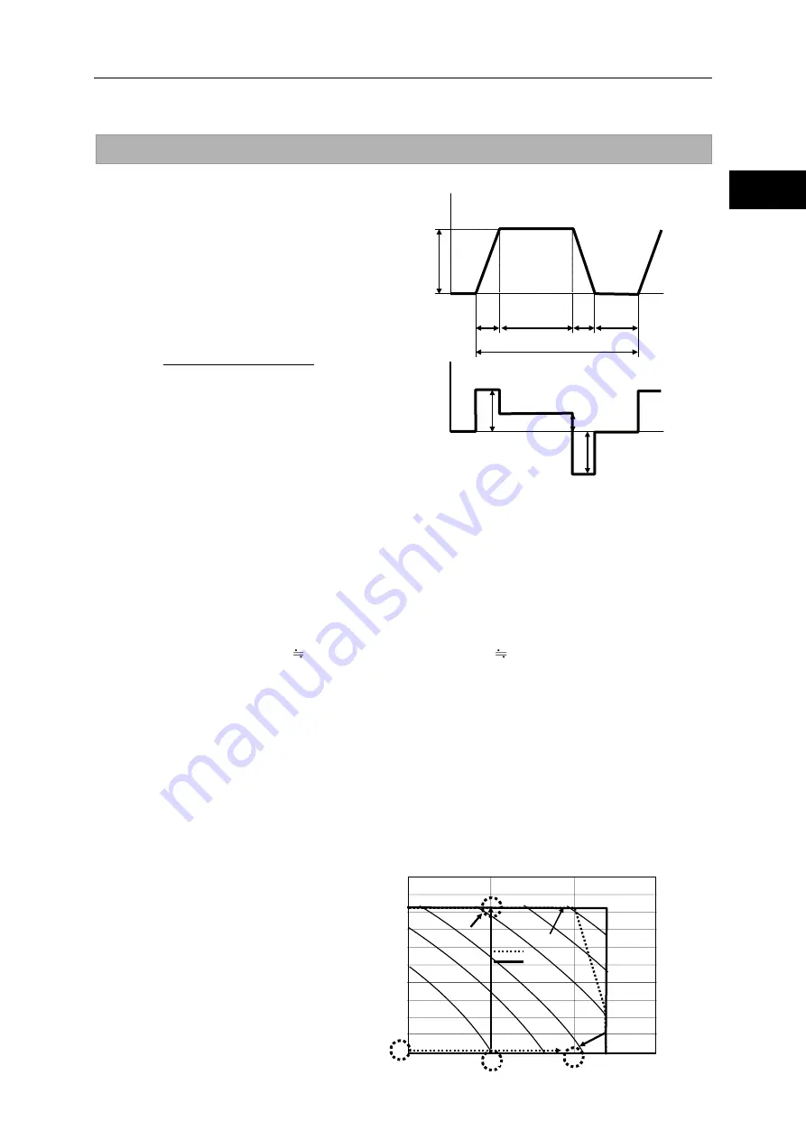
Duty cycles
To select the appropriate FHA-C mini series,
you must consider the change with time of
torque and rotation speed. Also more
importantly, when accelerating and decelerating,
you must take into account the flow of large
current for generating large torque, and the
large amount of heat that is generated.
Using the following formula, calculate the
duty: %ED when the actuator is operated
repeatedly in the drive pattern shown to the
right.
T
a
: Acceleration time from speed 0 to N (s)
t
d
: Deceleration time from speed N to 0 (s)
t
r
:
Operation time at constant speed N (s)
t:
Cycle time
(s)
K
La
: Duty factor for acceleration time
K
Lr
: Duty factor for operation time at constant speed
K
Ld
: Duty factor for deceleration time
Example 2: Calculating duty and getting K
La
, K
Lr
and K
Ld
With the duty factor graph for FHA-11C-50 as an example, calculate duty factors as follows.
The operating conditions are similar to those described in example 1. Accelerate an inertia load by the
maximum torque of the actuator and then let it move at a constant speed, followed by deceleration by
the maximum torque. The travel angle per cycle is 120° and the cycle time is 0.8 second.
1
KLa, KLd: Obtain KLa = KLd
≒
1.7 in the following figure from an average speed of 50
r/min when the rotation speed changes from 0 to 100 r/min.
2
KLr: is the inertia load, Tr 0. Then from the graph, KLr 0.9.
3
The travel angle is calculated from the area of the rotation speed vs. time diagram shown above.
In other words, the travel angle is calculated as follows:
θ = (N / 60) x {tr + (ta + td) / 2} x 360
Then, tr =θ / (6 x N) – (ta + td) / 2
Substituting θ = 120°, ta = 0.072(s), td = 0.046(s) and N = 100r/min from example 1 will be tr =
0.14(s).
4
Because the cycle time is 0.8 (s), the duty (%ED) is obtained as follows:
%ED = (1.7 x 0.072 + 0.9 x 0.14 + 1.7 x 0.048) / 0.8 x 100 = 41.2%
It is possible to drive the actuator continuously with this cycle time, because the %ED is less
than 100%.
If the %ED is over 100%,
the operation pattern
load (possible reduction)
actuator model No.
etc., must be reexamined.
100
t
t
K
t
K
t
K
ED
%
d
Ld
r
Lr
a
La
×
×
+
×
+
×
=
Time
ta
td
N
tr
Time
Rotation speed
t: Cycle time
ts
Ta
Tor
qu
e
Td
Tr
ts: Stopped time
Ta, Tr, Td: Output torques
(2) KLr
Rotation speed [r/min]
Tor
que
[N
m
]
Radiation plate: 150 x 150 x 6(mm)
■
FHA-11C-50
KL=0.33
0.67
1
9
7
6
5
4
3
2
0
1
10
1.5
2
2.5
8
150
100
50
0
Operable range
100V
200V
Содержание FHA - C mini Series
Страница 30: ...1 14 Cable specifications 1 21 1 2 3 4 5 6 7 8 9 10 11 Apx Outlines...
Страница 54: ...3 5 PL09 Magnetic pole detection level setting Installation 3 7 1 2 3 4 5 6 7 8 9 10 11 Apx Installation...
Страница 55: ...4 Option Options you can purchase as necessary are explained in this chapter 4 1 Extension cable 4 1 Chapter...
Страница 60: ...4 1 Extension cable Option 4 5 1 2 4 4 5 6 7 8 9 10 11 Apx Option...


